background image

20

TRUCLIMATE 500 INSTALLATION GUIDE 


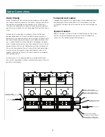
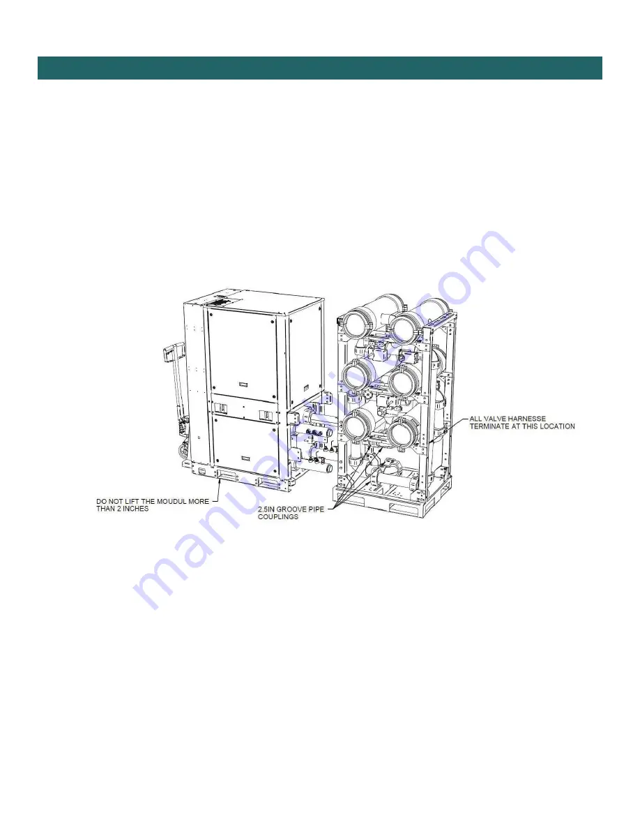
Chiller Installation: Removing Module from Bank of Units

1. 

Undo the 2.5” groove couplings, disconnect all 3-way valve harnesses and isolation valve harnesses.

2.  Slightly lift (2in maximum) the module and pull away from the bank. Make sure that the module sensors does not 

come into contact with any of the structural members of the header rack.

3.  Reassemble in the reverse order. Connect the all 3-way valves harnesses sand isolation valve harnesses by 

following the provided labels. Prior to re-starting the system verify that all valves are wired properly by manually 
changing the header rack modes and observing the 3-way valve orientation.

Содержание TruClimate 500

Страница 1: ...given supervision or instruction concerning use of the appliance by a person responsible for their safety Children should be supervised to ensure that they do not play with the appliance Keep this man...

Страница 2: ...e atmospheres Ensure that the leak detection equipment being used is suitable for use with all applicable refrigerants i e non sparking adequately sealed or intrinsically safe If any hot work is to be...

Страница 3: ...frigerant leaks A halide torch or any other detector using a naked flame shall not be used WARNING For appliances using A2L refrigerants connected via an air duct system to one or more rooms only auxi...

Страница 4: ...t a factory refrigerant leakage sensor If a permanent vent is used to exhaust air from A1 to EAmin Qmin the minimum volumet ric ow of air is provided in Table 1 Refrigerant Leak Detection and Mitigati...

Страница 5: ...7 28 5 276 470 T5HS080SN2 18 5 296 8 39 1178 109 4 236 21 9 306 7 28 5 276 470 T5HS030LN2 10 5 168 4 76 379 35 2 76 7 0 213 6 19 8 192 327 T5HS050LN2 19 0 304 8 62 1242 115 4 248 23 1 315 0 29 3 284...

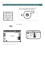
Страница 6: ...wer LED6 G External Relay Blower for Mitigation FIELD WIRING Light emitting diode Green Relay coil Polarized connector Factory Low voltage wiring Factory Line voltage wiring Field low voltage wiring F...

Страница 7: ...the airflow rate established in the Mechani cal Ventilation Rate chart The area requirement for the room size where the ventilation is directed must be equal or larger to the area in established in t...

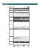
Страница 8: ...t water temperature F C Max inlet water pressure in water Pa CK BOX Heater Model Supply Circuit KW Min CIR AMP Max Fuse Max BRKR 0 0 Unit Nomenclature and Serial Number Unit Voltage Fuse Breaker Size...

Страница 9: ...ER 28 0 55 50 with Isolation Valve DUAL SCROLL MODULE STANDALONE DIMENSIONS 53 5 12 5 28 8 9 0 9 2 24 6 9 7 23 3 ANSI 150 FLANGE 46 3 1 7 SOURCE OUTLET SOURCE INLET LOAD INLET LOAD OUTLET 2 3 1 4 Conf...

Страница 10: ...71 6 6 Pipe Dedicated 8 inch 38 0 77 5 85 1 9 4 28 4 35 3 52 4 72 3 6 inch 30 0 76 5 77 1 7 5 22 5 38 0 51 0 71 6 4 Pipe Reversing 6 inch 30 0 76 5 77 1 7 5 22 5 30 5 71 6 Pipe Configurations Configur...

Страница 11: ...73 29 34 00 27 69 16 4 32 2 45 2 61 1 20 3 TYP 1 2 3 4 SCH 40 GROOVE PIPE 6IN AND 8IN Configuration Header Index 1 2 3 4 4 Pipe Standard with Reversible Chiller Load Outlet Load Inlet Source Outlet So...

Страница 12: ...00 INSTALLATION GUIDE Dimensional Data Banked Units POWER FEED OPTIONAL SINGLE POINT PANEL RIGHT INSTALLATION SHOWN 18 0 457mm 6 4 164mm REQUIRED TEMPERATURE HEADER LEFT OR RIGHT CONFIGURATION 16 7 42...

Страница 13: ...13 TRUCLIMATE 500 INSTALLATION GUIDE Dimensional Data Banked Units 33 0 838mm NUMBER OF MODULES X 33 9 4 238mm 73 2 1860mm 82 1 2086mm...

Страница 14: ...ata Service Clearance Banked Units 24 0 610mm 24 0 610mm 30 0 762mm 53 25 INCH REQUIRED FOR REMOVING THE MODULE 30 0 762mm 24 0 610mm RECOMMENDED AVOID INSTALLING PIPING ABOVE THE CHILLER ELECTRICAL P...

Страница 15: ...ravity TRUCLIMATE 500 MODULAR MODEL TYPE FIXED SPEED FIXED SPEED FIXED SPEED FIXED SPEED FIXED SPEED FIXED SPEED FIXED SPEED VARIABLE SPEED VARIABLE SPEED MODEL SIZE 020 030 040 050 060 070 080 030 05...

Страница 16: ...2 NPT BUNG CUT GROOVE PER VIC 25 01 REV J CUT GROOVE PER VIC 25 01 REV J CUT GROOVE PER VIC 25 01 REV J CUT GROOVE PER VIC 25 01 REV J C WATER PRESSURE SENSOR WATER TEMP SENSOR TYPE II WATER PRESSURE...

Страница 17: ...R VIC 25 01 REV J WATER PRESSURE SENSOR OPTIONAL WATER TEMP SENSOR TYPE II 2 75 5 25 C B Configuration A in B in C in 8 inch 8 6 4 9 7 1 6 inch 6 6 3 9 6 1 TEMPERATURE WEATHER P T PORT DEFAULT OR OPTI...

Страница 18: ...7 25 7 82 18 50 8 39 18 50 8 39 10 50 4 76 19 00 8 62 Factory Charge Reversible lbs kg 9 00 4 08 10 50 4 76 14 50 6 58 16 00 7 26 17 25 7 82 18 50 8 39 18 50 8 39 10 00 4 54 Compressor Single Speed Sc...

Страница 19: ...et bolts on the bracket closer to the previously installed chiller are removed 5 After the second chiller is installed removed the rest of the shipping bolts 6 Follow this sequence for all units 7 Ins...

Страница 20: ...pull away from the bank Make sure that the module sensors does not come into contact with any of the structural members of the header rack 3 Reassemble in the reverse order Connect the all 3 way valve...

Страница 21: ...d Secure a 3rd set of straps to top rear header rack bracket 6 Pipe and 4 pipe reversing ONLY Other configurations do not require a 3rd strap 2 Always use spreader bars The sound enclosure of the chil...

Страница 22: ...and can still be moved side to side This freedom of movement is neces sary when installation the second floating flange 1 2 NPT BUNG 1 2 NPT BUNG 1 2 NPT BUNG 1 2 NPT BUNG CUT GROOVE PER VIC 25 01 RE...

Страница 23: ...re 2a View of proper gasket installation with flange Figure 3 Section view of floating flange 2 Install both floating flange gaskets on the small pipes The gasket must be installed as shown DO NOT LUB...

Страница 24: ...Figure 4 Failure to center the ring correctly can cause a leak 4 Rotate the valve assembly to a desired angle or to the suggested orientation in the assembly drawing shown in Figure 5 Once the ring is...

Страница 25: ...and care should be implemented in order to ensure and maintain a clean system Water should be treated and clean per necessary standards before start up is scheduled Each water header is equipped stand...

Страница 26: ...0 5 ppm Ammonia Nitrate Less than 0 5 ppm Less than 0 5 ppm Less than 0 5 ppm Ammonia Hydroxide Less than 0 5 ppm Less than 0 5 ppm Less than 0 5 ppm Ammonia Sulfate Less than 0 5 ppm Less than 0 5 p...

Страница 27: ...d to be ran from the single point disconnect to each module in the field High Voltage Ground Item Number P N Description Quantity 1 47P921 05U 5 Wireway Elbow 1 2 47P921 06U Wireway Support Bracket 6...

Страница 28: ...hall be taken not to overfill the REFRIG ERATING SYSTEM Prior to recharging the system it shall be pressure tested with the appropriate purging gas The system shall be leak tested on completion of cha...

Страница 29: ...ment shall be in good working order with a set of instructions concerning the equipment that is at hand and shall be suitable for the recovery of the flammable refrigerant If in doubt the manufacturer...

Страница 30: ...ss a problem is suspected Unit Amp Draw Line Voltage Subcooling Superheat Evaporator Condenser Entering Hot Water o F Entering Water Pressure PSIG Leaving Hot Water o F Leaving Water Pressure PSIG Ent...

Страница 31: ...31 TRUCLIMATE 500 INSTALLATION GUIDE Notes...

Страница 32: ...reserves the right to change design and speci cations without notice Product TruClimate 500 Type Water Cooled Chiller 60 Hz Size 20 80 Tons Document Installation Manual IG1901WW 12 23 IG1901WW Manufac...

Страница 33: ...les ci ne b n ficient d une surveillance ou d instructions concernant l utilisation de l appareil de la part d une personne responsable charg e de veiller leur s curit Les enfants doivent tre sous sur...

Страница 34: ...eur de r frig rant appropri avant et pendant le travail afin de s assurer que le technicien est conscient de la pr sence d atmosph res potentiellement toxiques ou inflammables Assurez vous que le mat...

Страница 35: ...t des r frig rants A2L reli s par un r seau de conduits d air une ou plusieurs salles seuls les dispositifs auxiliaires approuv s par le fabricant de l appareil ou d clar s appropri s au r frig rant d...

Страница 36: ...e de r frig rant d usine Si un vent permanent est utilis pour vacuer l air de A1 EAmin Qmin le d bit volum trique minimal d air est indiqu dans le Tableau 1 0 vent permanent S RIE DE REFROIDISSEURS MO...

Страница 37: ...109 4 236 21 9 306 7 28 5 276 470 T5HS080SN2 18 5 296 8 39 1178 109 4 236 21 9 306 7 28 5 276 470 T5HS030LN2 10 5 168 4 76 379 35 2 76 7 0 213 6 19 8 192 327 T5HS050LN2 19 0 304 8 62 1242 115 4 248 23...

Страница 38: ...tion C BLAGE SUR SITE Diode lectroluminescente verte Bobine de relais Connecteur polaris L gende G 3 2 C blage basse tension d usine C blage de tension de ligne d usine C blage basse tension sur site...

Страница 39: ...anique La superficie requise pour la taille de la salle dans laquelle la ventilation est dirig e doit tre gale ou sup rieure la superficie d finie dans le Tableau de la surface minimale de salle venti...

Страница 40: ...ax inlet water temperature F C Max inlet water pressure in water Pa CK BOX Heater Model Supply Circuit KW Min CIR AMP Max Fuse Max BRKR 0 0 Unit Nomenclature and Serial Number Unit Voltage Fuse Breake...

Страница 41: ...23 3 ANSI 150 FLANGE 46 3 55 50 with Isolation Valve 1 7 SOURCE OUTLET SOURCE INLET LOAD INLET LOAD OUTLET 2 3 1 4 Configuration Index de collecteur 1 2 3 4 4 tuyaux standard avec refroidisseur r ver...

Страница 42: ...Configurations de tuyaux Configuration Index de collecteur 1 2 3 4 5 6 6 tuyaux standard Orifice d entr e source Orifice de sortie source Orifice d entr e froide Orifice de sortie froide Orifice d ent...

Страница 43: ...Configuration Index de collecteur 1 2 3 4 4 tuyaux standard avec refroidisseur r versible Orifice de sortie de charge Orifice d entr e de charge Orifice de sortie source Orifice d entr e source 4 tuy...

Страница 44: ...TALLATION SHOWN 18 0 457mm 6 4 164mm REQUIRED TEMPERATURE HEADER LEFT OR RIGHT CONFIGURATION 16 7 423mm 40 5 1029mm TEMP RATURE REQUISE CONFIGURATION GAUCHE OU DROITE DU COLLECTEUR INSTALLATION DE DRO...

Страница 45: ...ATION DU TRUCLIMATE 500 Donn es dimensionnelles unit s en s rie 33 0 838mm NUMBER OF MODULES X 33 9 4 238mm 73 2 1860mm 82 1 2086mm NOMBRE DE MODULES X 33 PO 82 1 po 2086 mm 9 4 po 238 mm 73 2 po 1860...

Страница 46: ...0 0 762mm 24 0 610mm RECOMMENDED AVOID INSTALLING PIPING ABOVE THE CHILLER ELECTRICAL PANEL 24 0 610mm RECOMMENDED 30 0 762mm RECOMMENDED 24 0 po 610 mm 24 0 po 610 mm 30 0 po 762 mm 24 0 po 610 mm RE...

Страница 47: ...060 070 080 030 050 SHIPPING WEIGHT LBS kg 1847 838 1889 857 1921 871 1979 898 2039 925 2046 928 2139 970 1969 893 1 2039 924 9 15 po 378 mm 35 po 890 mm 26 po 669 mm CENTRE DE GRAVIT TRUCLIMATE 500 M...

Страница 48: ...EN FONCTION DE VIC 25 01 REV J RAINURE TAILL E EN FONCTION DE VIC 25 01 REV J RAINURE TAILL E EN FONCTION DE VIC 25 01 REV J RAINURE TAILL E EN FONCTION DE VIC 25 01 REV J C CAPTEUR DE PRESSION D EAU...

Страница 49: ...25 01 REV J CAPTEUR DE PRESSION D EAU EN OPTION CAPTEUR DE TEMP RATURE D EAU TYPE II 2 75 5 25 C B Configuration 8 pouces 8 6 4 9 7 1 6 pouces 6 6 3 9 6 1 TEMP RATURE M T OROLOGIQUE B po C po A po PO...

Страница 50: ...00 3 63 10 00 4 54 13 75 6 24 16 00 7 26 17 25 7 82 18 50 8 39 18 50 8 39 10 50 4 76 19 00 8 62 R versible avec charge d usine lb kg 9 00 4 08 10 50 4 76 14 50 6 58 16 00 7 26 17 25 7 82 18 50 8 39 18...

Страница 51: ...n du deuxi me refroidisseur retirez le reste des boulons d exp dition 6 Suivez cette s quence pour toutes les unit s 7 Installez les collecteurs de d rivation et de temp rature conform ment aux boucle...

Страница 52: ...e n entrent pas en contact avec les l ments du support de collecteur 3 R assemblez tout dans l ordre inverse Raccordez tous les faisceaux de valves 3 voies et les faisceaux de vannes d isolement en su...

Страница 53: ...onfigurations ne n cessitent pas de troisi me sangle 2 Toujours utiliser les palonniers L enceinte d insonorisation peut tre endommag e si le palonnier n est pas utilis 3 Les poches avant du refroidis...

Страница 54: ...e de l autre Cette libert de mouvement est n cessaire lors de l installation d une deuxi me bride flottante BOUCHON NTP 1 2 PO BOUCHON NTP 1 2 PO BOUCHON NTP 1 2 PO BOUCHON NTP 1 2 PO RAINURE TAILL E...

Страница 55: ...e de l installation correcte du joint d tanch it Figure 3 Vue en coupe de la bride flottante 2 Installez les deux joints d tanch it de la bride flottante sur les petits tuyaux Le joint d tanch it doit...

Страница 56: ...e cela risque de provoquer des fuites 4 Faites pivoter l ensemble des vannes l angle d sir ou selon l orientation sugg r e dans le sch ma d ensemble pr sent la figure 5 Une fois que la bague est centr...

Страница 57: ...Chaque collecteur d eau est quip de mani re standard d un capteur de temp rature pour les temp ratures de l eau d alimentation et de l eau de retour des performances des unit s Le syst me comprend ga...

Страница 58: ...Hydroxyde d ammonium Moins de 0 5 ppm Moins de 0 5 ppm Moins de 0 5 ppm Sulfate d ammonium Moins de 0 5 ppm Moins de 0 5 ppm Moins de 0 5 ppm Moins de 1000 ppm 1000 1500 ppm 1000 1500 ppm Indice LSI 0...

Страница 59: ...U Wireway end Plate 1 4 47P921 08U 5 Wireway Assembly 3 5 79D661 02 Single Point Power R H 460 V 3 Phase 1 6 Truclimate 500 WC Scroll 3 7 LT150P 1 1 2 Inch Non Metallic Liquidtight Bullet Connector 6...

Страница 60: ...t de veiller tr s attentivement ne pas trop remplir le SYST ME FRIGORIFIQUE Avant de recharger le syst me il doit tre soumis un essai de pression avec le gaz de purge appropri Le syst me doit tre soum...

Страница 61: ...de r cup ration doit tre en bon tat de fonctionnement et inclure des instructions concernant le mat riel disponible et doit convenir la r cup ration du r frig rant inflammable En cas de doute consulte...

Страница 62: ...n probl me est suspect Amp rage de l unit Tension compos e Sous refroidissement Surchauffe vaporateur Condenseur Entr e eau chaude o F Pression de l eau l entr e Sortie eau chaude o F Sortie pression...

Страница 63: ...31 MANUEL D INSTALLATION DU TRUCLIMATE 500 Notes...

Страница 64: ...l se r serve le droit de modi er la conception et les sp ci cations sans pr avis Produit TruClimate 500 Type Refroidisseur eau 60 Hz Taille 20 80 tonnes Document Manuel d installation IG1901WW 01 24 I...

Отзывы: