


INSTAL
LATION
Refill Flow Control Assembly or Refill Port Plug
Control valves that are setup for backwash only come equipped with a refill port plug. The refill port plug has
no regenerant line connection.
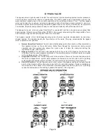
Control valves that use a regenerant come equipped with a 3/8” refill flow control assembly. To switch to the
½” refill flow control assembly, remove the refill flow control and retainer (from the 3/8” refill elbow) by
twisting and pulling out. Insert the refill flow control and retainer into the ½” refill elbow.
To complete the regenerant line connection, orientate the outlet in the desired direction and push the plastic
insert into the polytube. Push the polytube into the nut. Do not use pipe dope or other sealants on threads.
The threads for the compression nut do not need Teflon tape. Tighten the nut securely to create a pressure
tight connection. A pliers or crescent wrench may be used to tighten or unscrew the nut. The nut, gripper
and retainer sleeve is a 3 piece assembly that can come apart if removed from the elbow body. Parts must
be reassembled exactly as shown in refill flow control assembly drawing to function properly. If the nut is
completely removed from the body, slip the nut, plastic gripper and retainer sleeve on to the tube then
tighten on to the fitting.
Drain Line Flow Control and Fitting Assembly
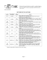
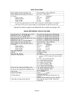
To determine which drain line flow control to use, obtain media bed expansion tables from the media
manufacturer, choose a water temperature and look up the desired backwash rate per square foot of bed
area. Then calculate the backwash rate using the desired tank diameter. Using Table 7, choose the drain
line flow control that has the backwash flow rate closest to the calculated backwash rate. If a manufacturer
chooses to use an external drain line flow control, use an elbow fitting that does not contain a hole.
If the drain line is a 5/8” flexible polytube, slide the nut onto the polytube, then place the polytube insert into
the end of the polytube and tighten the nut on to the ¾” drain line fitting. The nut is only designed for use
with flexible polytube. Use other nuts if attaching different materials.
To access the drain line flow control remove the locking clip by pulling it straight out. Pull fitting out and
replace the locking clip so that it is not misplaced. The drain line fitting is pressed in and has an o-ring seal.
In the ¾” elbow, the white flow control retainer is pressed in and has an o-ring seal. The retainer can be
removed by rotating and pulling. The flow control can be removed by prying upward with a small blade flat
screwdriver in one of the slots on the side. The drain line flow control and retainer can be chemically cleaned
in dilute sodium bisulfite or vinegar, or replaced. Do not use a wire brush to clean the flow control or the
washer. The washers are identified with three numbers, which correspond to the flow rate. When reinstalling
make sure the identifying number and the rounded inside diameter on the washer is visible when seated in
the retainer. The white flow control washer retainer can also be removed and cleaned. Push the retainer in
firmly when reinstalling.
In the 1” straight fitting, the retainer is the fitting. Unscrew the nut to access the flow control. The drain line
flow control and the fitting can be chemically cleaned or replaced. Do not use a wire brush to clean the flow
control or the fitting.
Do not use Vaseline, oils, or other unacceptable lubricants on o-rings. A silicone lubricant may be used on
the black o-ring. Use a pliers or crescent wrench to tighten or unscrew the nut. Do not use a pipe wrench to
tighten or loosen nut. Do not use pipe dope or other sealants on threads. Use Teflon tape on the threads of
the drain line control fitting when installing ¾” NPT or 1” straight fitting.
Page 12