8
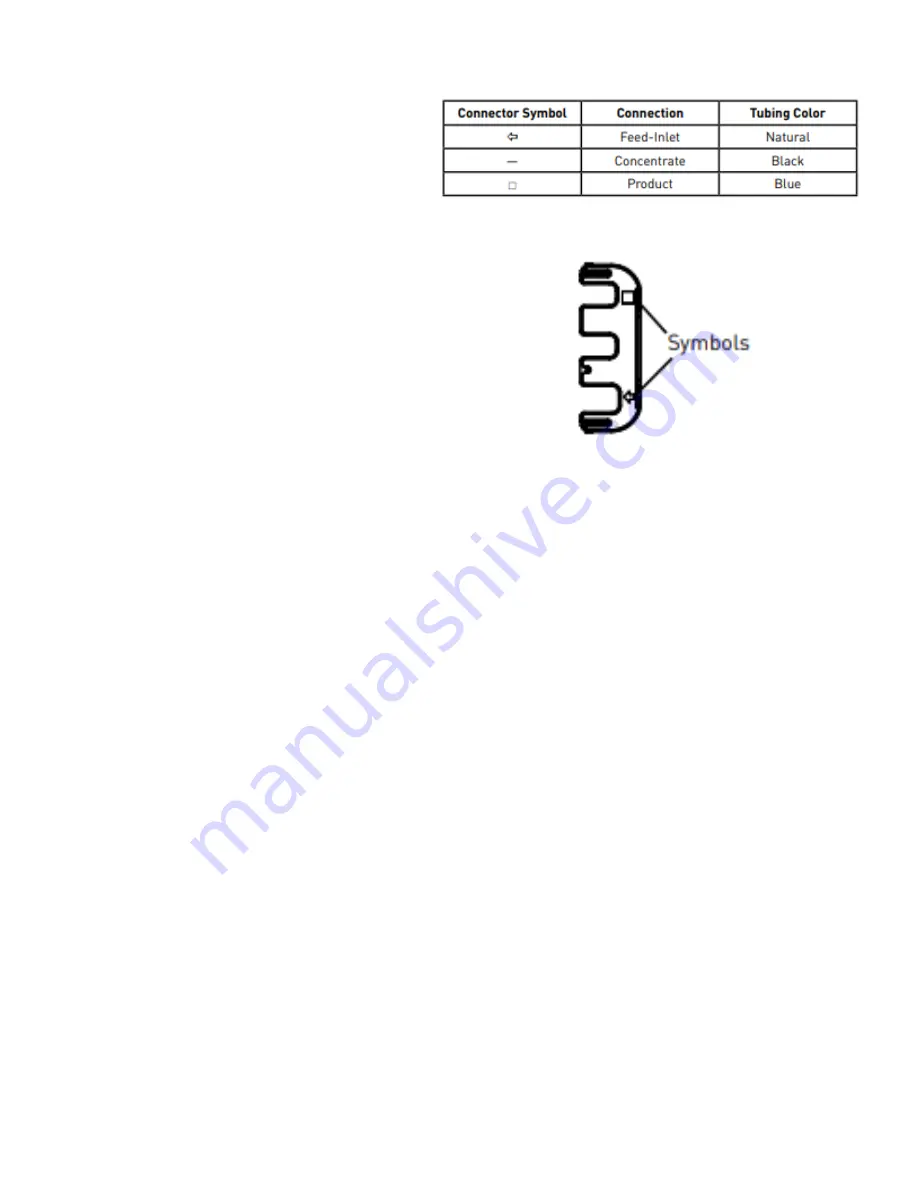
9. Figure 3 details the coding system for the fitting
connections. Each fitting has a unique “keyed”
socket on the manifold. Each fitting also has a
graphic symbol molded into the elbow with a
corresponding symbol on the manifold. The
locking clip also has the same markings (Figure 4).
10. Insert the float switch wire (located on top of the
storage tank) through one of the open cord grips
on the control panel.
11. Land the (2) float switch wires on their appropriate
terminals. The appropriate terminals are 7 & 8.
Either wire can be landed on either terminal. Polarity
does not matter. For additional wiring information,
see appendix B and C.
12. Connect the plastic tubing (located on top of the
storage tank) to the ozone generator output. The
ozone generator output is located on the bottom of
the ozone generator.
13. Connect the blue 3/8” tubing from the permeate outlet
on the skid assembly to the connection on the top of
the storage tank.
START-UP STEPS
1.
Once all plumbing connections are completed, and the system is plugged in, check to make certain the drain flow control
valve (gray valve with black circular handle), is in the fully open position.
2.
For WHRO-700MAX systems only, open the filter inlet valve and depress the air purge button located on the top of the tank
until a steady stream of liquid comes out of the cartridge. As the cartridge fills up with water, air will be vented while the air
purge button is depressed. After a steady stream of liquid comes out of the filter, open the filter outlet valve.
3.
PRESSURIZE: Turn the control switch on the control panel to “Run”. This will open the motorized ball valve.
4.
PRESSURIZE: Slowly open the feed valve to the RO system. As the system begins to pressurize, you will notice air bubbles
in the DRAIN and PRODUCT flow meters and the pressure will begin to rise.
5.
PRESSURIZE: Slowly increase the amount of water feeding the RO system until the feed valve is completely open. At this
point, most of the water should be passing through the DRAIN flow meter. Allow the system to run this way for at least 30
minutes. This will flush the membranes.
6.
CHECK FOR LEAKS: During this initial start-up time, check for leaks. As a result of shipping, it is possible that some of the
fitting and tubing connections could be loose.
7.
CHECK FOR LEAKS: Once you have checked for leaks and corrected all you have found, adjust the drain flow control valve
so that the DRAIN flow and PRODUCT flow ratio is in line with Table 2.0 in the “System Recovery” section.
8.
FILL TANK: At this time, the storage tank is slowly filling with RO purified water (PRODUCT WATER). On a standard system,
the production rate is approximately 0.50 GPM. In order to test the pump and make certain the tank is clean, consider adding
tap water to the tank so that it is at least ½ full.
9.
PRIME PUMP: Once the water level in the tank is above the top of the pump, prime the pump. To do this, open the tank outlet
valve and, with the power to the pump turned off, slowly unscrew the air relief port on the top of the pump. If there is enough
water in the storage tank, water will begin to spew out of the port. Allow sufficient water to pour out to make certain no air
remains in the pump. Close the tank valve, screw the port cap back on the pump, and open the tank valve.
NOTE: If the pump does not prime by the method described above, water may be manually added to the priming port to
fill the entire pump cavity with water.
10.
TEST FLOAT: While you continue to add water to the storage tank, reach inside the tank and manually lift the float. With the
float elevated toward the top of the storage tank, the motorized valve should close cutting off the water supply to the system.
Repeat this step 3 to 4 times to confirm the system successfully turns on and off. This can be observed by:
a.
No more water entering the storage tank
Figure 4
Figure 3
Содержание WHRO-700
Страница 2: ...2 This page intentionally left blank...
Страница 5: ...5 SYSTEM DIAGRAM...
Страница 6: ...6 TYPICAL INSTALLATION DIAGRAM...


