01.11.22, 14:00
Firebox T80 Hardware Guide
https://www.watchguard.com/help/docs/help-center/en-US/Content/en-US/Hardware-Guides/firebox-t80-hardware-guide.html?cshid=10002
5/18
The fan opening includes a stationary shroud that protects the fan and prevents access to the fan
blades from outside the device.
Do not insert a pointed object to attempt to touch or move the fan blades.
For more information about fan operation and status, see
Firebox T80 Fan Operation and Diagnostics
in the
WatchGuard Knowledge Base.
Rear View
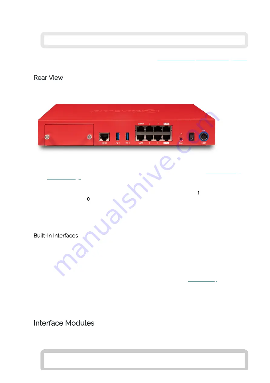
Rear view of the Firebox:
Reset Button
This resets the device. To restore the device to factory-default settings, see
Power Switch
Controls the power supplied to the device. Move the switch to position
1
to power on the
device, or position
0
to power it off.
Power Input
An AC power adapter is included with your device. Connect the AC adapter to the device and to
a power source. The power supply tip is plus (+) polarity. Use only the supplied AC power
adapter.
Built-In Interfaces
Serial Port (Console)
The leftmost port is an RJ45 serial console port. An RJ45 serial cable is not included with the
device.
USB Interfaces
The device includes two USB interfaces. Connect a USB storage device for USB backup and
restore, or to store a support snapshot. For more information, see
Network Interfaces
The Ethernet interfaces have standard RJ45 connectors and support link speeds of 10, 100, or
1000 Mbps. These interfaces are labeled 0/WAN, 1/LAN, 2, 3, 4, 5, 6-PoE, 7-PoE. Interfaces 6 and
7 are PoE (Power over Ethernet) interfaces, compliant with the IEEE 802.3at standard.
Interface Modules
The Firebox T80 includes an expansion bay for additional interface modules. You must install the
expansion module before you can configure the interfaces.
Expansion modules are not hot-swappable. To avoid damage to the system,
power off the Firebox before you install or remove expansion modules.


