background image

18

WatchGuard Firebox M370/470/570/670

Hardware Installation

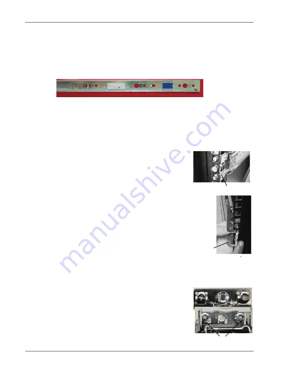
Attach the inner rails and front ear brackets to the Firebox

Use these steps to attach the inner rails and front mounting brackets to the Firebox.

1. Locate the six short screws from the rail kit.

2. Put the inner rail against one side of the Firebox with the small blue release tab toward the front of the 

Firebox, facing out. 

3. Align the screw holes in the rail with the three screw holes on the side of the Firebox. The inner rail 

extends out from the back of the Firebox.

4. Attach the inner bracket to the Firebox with three of the short screws provided in the rail kit.

5. Use two of the short screws included with the front ear brackets to attach an ear bracket to the front of 

the Firebox on one side. 

6. Repeat these steps to attach the other inner rail and ear bracket to the other side of the Firebox. 

Attach the outer rails to the rack

You do not need to use screws to attach the rails to the network rack. 
To attach rails to the rack, align the screw heads on each end of the rail 
with holes in the rack and then latch the rail to the front and back of 
the rack. 

1. Align the front of one rail with three available screw holes in the 

front edge of the rack.

2. Press the end of the rail toward the rack until the metal latch in 

the center of the rail clicks into place around the inner edge of 
the rack.

3. Align the rear of the outer rail with three available screw holes in 

the rear of the rack.

4. Pull the latch handle slightly toward the center of the rack and 

snap it into place around the inner edge of the rack.

5. Repeat these steps to install the second sliding rail in the rack.

Install alternate screws on the rails

If the screw heads on the rail ends are too large to fit through the 
holes in your network rack, use the eight screws with smaller heads
(included with the rail kit) to replace the screws on the rails before 
you install the rails in the rack. 

1. Remove the outer two screws on the front of the rail

and replace them with two smaller screws included 
with the rail kit.

2. Remove the two screws from the back of the rail and replace 

them with two smaller screws included with the rail kit.

3. Repeat these steps to install smaller screws on the second rail.

4. Install the rails in the rack as described in the previous procedure.

Front latch

Rear latch
handle

Remove and replace

Remove and replace

Содержание Firebox M470

Страница 1: ...WatchGuard Firebox M370 470 570 670 Hardware Guide WL6AE8...

Страница 2: ...y other mark listed as a trademark in the Terms of Use portion of the WatchGuard Web site that is used herein are either registered trademarks or trademarks of WatchGuard Technologies Inc and or its s...

Страница 3: ...de s curit 12 Aviso De Seguridad 13 Chapter 2 Hardware Installation 15 Rack Mount Installation 15 Interface Module Installation 20 Chapter 3 Legal and Regulatory Information 21 Limited Hardware Warran...

Страница 4: ...iv WatchGuard Firebox M370 470 570 670...

Страница 5: ...layers of defense This guide introduces the Firebox M370 470 570 670 an RoHS compliant lead free hardware product offered by WatchGuard Fireware OS The Firebox M370 470 570 670 uses WatchGuard s next...

Страница 6: ...670 also have a slot where you can install an additional interface module The supported interface modules are described in the Hardware Description section M370 M470 M570 M670 Processor Intel Skylake...

Страница 7: ...on page 15 Put it in a secure area such as a locked room to block the device from people who do not have permission to use it Connect it to a conditioned power supply to prevent damage from sudden po...

Страница 8: ...hard disk this indicator is yellow Power Button The Power button on the front of the Firebox is lit to indicate power status It is green when the Firebox is powered on and red when power is available...

Страница 9: ...ndicator shows the interface connection status The left indicator shows interface activity Interface Modules To add more interfaces to your Firebox M470 M570 or M670 you can install an interface modul...

Страница 10: ...terface Module The eight RJ45 interfaces are numbered from 0 to 7 Each RJ45 interface has two indicators The right indicator shows the interface link status The left indicator shows interface activity...

Страница 11: ...icators that point down show the status of the lower interface For each interface the left indicator shows activity and the right indicator shows the link status You can purchase compatible SFP transc...

Страница 12: ...dicator shows link status the right indicator shows activity You can purchase compatible SFP transceivers from an authorized WatchGuard reseller SFP multi mode transceiver 10GBase SR 1000Base SX 850 n...

Страница 13: ...new configuration you can reset your device Make sure you back up your device configuration before you reset your device in case you want to restore it in the future To reset your device 1 If necessar...

Страница 14: ...act with a voltage point or short out a part it can result in fire or electrical shock If the equipment is supplied with a three conductor AC power cable the power cable must be plugged in to an appro...

Страница 15: ...r anderweitig blockiert sind Die Ventilation verhindert ein berhitzen des Ger tes Stecken Sie niemals Gegenst nde irgendwelcher Art in Schlitze oder ffnungen des Ger tes Wenn Sie Kontakt mit einem spa...

Страница 16: ...ent la surchauffe de l appareil N ins rez jamais d objet de quelque sorte dans les fentes d ouverture de cet quipement Si vous faites contact avec un point sous tension ou court circuitez un composant...

Страница 17: ...able de alimentaci n No obstruya las aberturas de ventilaci n Estas aberturas evitan el sobrecalentamiento de la m quina Nunca introduzca objetos de ning n tipo en las ranuras o aberturas del equipo E...

Страница 18: ...14 WatchGuard Firebox M370 470 570 670 Hardware Specifications...

Страница 19: ...e included front ear brackets or the rack rail kit to install your Firebox in a network rack Your Firebox ships with two front ear brackets The included front ear bracket kit includes 2 long front ear...

Страница 20: ...all the device in a rack make sure that the amount of air flow required for safe operation of the equipment is not compromised Mechanical Loading When you mount the device in the rack avoid hazardous...

Страница 21: ...f the Firebox on one side 4 Use the other four screws to attach the other front ear bracket to the other side of the Firebox 5 Position the Firebox in the network rack so that the holes in the bracket...

Страница 22: ...rail to the front and back of the rack 1 Align the front of one rail with three available screw holes in the front edge of the rack 2 Press the end of the rail toward the rack until the metal latch i...

Страница 23: ...mpletely into the rack until the front ear brackets touch the front of the rack 5 You can use the larger screws included with the rack ears to attach the rack ear brackets to the rack Remove the Fireb...

Страница 24: ...wo captive screws on the interface module to attach the interface to the Firebox 6 Reconnect the power cables to the Firebox The Firebox starts automatically When the Firebox starts Fireware automatic...

Страница 25: ...reby release WatchGuard from any liability for performance of enforcement of or damages or other relief on account of any such warranties or any breach thereof 2 REMEDIES If any Product does not compl...

Страница 26: ...f the 1980 United Nations Convention on Contracts for the International Sales of Goods as amended shall not apply You agree not to directly or indirectly transfer the Product or use of the product or...

Страница 27: ...OLVWHG EHORZ FRQIRUP WR WKH XURSHDQ 8QLRQ GLUHFWLYHV DQG VWDQGDUGV LGHQWLILHG LQ WKLV GHFODUDWLRQ 3URGXFW V DWFK XDUG 0RGHOV LUHER 0 0 0 0 DUGZDUH 0RGHO 8 LUHFWLYH V RZ 9ROWDJH OHFWURPDJQHWLF RPSDWLE...

Страница 28: ...y cause harmful interference to radio communications Operation of this equipment in a residential area is likely to cause harmful interference in which case the user will be required to correct the in...

Страница 29: ...policy REACH Registration Evaluation Authorization and restriction of Chemicals came into effect on June 1st 2007 REACH is Europe s new chemicals legislation which is applicable in all 27 EU Member S...

Страница 30: ...voquer un fonctionnement ind sirable Japan VCCI Notice Class A ITE Taiwan Class A Notice Mexico Notice La operaci n de este equipo est sujeta a las siguientes dos condiciones 1 es posible que este equ...

Страница 31: ...find full licensing information in the product documentation on our public web site at www watchguard com help documentation To get the source code covered by this license contact WatchGuard Technica...

Страница 32: ...28 WatchGuard Firebox M370 470 570 670 Legal and Regulatory Information...

Отзывы: