background image

Firebox System Area

Hardware Guide

21

Reset Firebox passphrases when you do not know or have forgotten 
them

Fireboxes shipped before LiveSecurity System 4.1 shipped with the 
original, standard functionality called the read-only system area. 
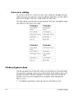
Fireboxes shipped with LiveSecurity System 4.1 or later contain both the 
older functions and a new set of features designed to enhance usability, 
called the enhanced system area.

Read-only system area

The Firebox III has a read-only system area that the unit can be booted 
into using the serial cable shipped with the Firebox. When a Firebox is 
running from the read-only system area, the Sys B light and the Armed 
light are both illuminated.

With the Firebox running the read-only system area, use one of two 
methods to initialize the Firebox and prepare it for configuration:

Factory default switch on back

Out-of-band, using a modem

Direct, using a serial cable

However, do not attempt to use the read-only system area configuration 
file as a base or template for your working configuration. It will not work. 
You must create a new configuration file using the QuickSetup Wizard or 
open an existing configuration file.

Enhanced System Mode

By default, Firebox III boots into an Enhanced System Mode. When a 
Firebox is running from the Enhanced System Mode, the Sys A light on 
the front panel flickers yellow in a repeating pattern.

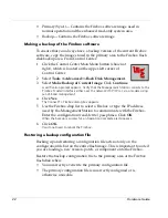
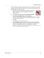
Managing flash disk memory

The Flash Disk Management Tool performs specific tasks involving the 
Firebox flash memory. The flash disk is divided into three areas:

System (SysB)– Contains a permanently stored, basic Firebox 
software image with the passphrase 

wg

.

Содержание Firebox 2500 Series

Страница 1: ...Firebox III Hardware Guide Firebox 500 Firebox 700 Firebox 1000 Firebox 2500 Firebox 4500...

Страница 2: ...r MUVPN FireChip HackAdmin HostWatch Make Security Your Strength RapidCare SchoolMate ServiceWatch Smart Security Simply Done Vcontroller VPNforce The W G logo are either registered trademarks or trad...

Страница 3: ...nnecting a Firebox 8 Running the QuickSetup Wizard 11 Post installation steps 12 Hardware Description 12 Firebox III front view all models except Model 500 and 700 13 Firebox III front view Model 500...

Страница 4: ...iv Hardware Guide Firebox System Area 20 Read only system area 21 Enhanced System Mode 21 Managing flash disk memory 21...

Страница 5: ...n the front of the Firebox Limited Hardware Warranty This Limited Hardware Warranty the Warranty applies to the enclosed WatchGuard hardware product the Product BY USING THE PRODUCT YOU AGREE TO THE T...

Страница 6: ...od Any Product component part or other item replaced by WatchGuard becomes the property of WatchGuard WatchGuard shall not be responsible for return of or damage to any software firmware information o...

Страница 7: ...AGES THIS SHALL BE TRUE EVEN IN THE EVENT OF THE FAILURE OF ANY AGREED REMEDY 5 Miscellaneous Provisions This Warranty will be governed by the laws of the state of Washington U S A without reference t...

Страница 8: ...tion This device has been tested and found to comply with limits for a Class A digital device pursuant to Part 15 of the FCC Rules Operation is subject to the following two conditions This device may...

Страница 9: ...ent indicates that it is in compliance with the Electromagnetic Compatibility EMC directive and the Low Voltage Directive LVD of the European Union EU Industry Canada This Class A digital apparatus me...

Страница 10: ...6 Hardware Guide Taiwanese Notice VCCI Notice Class A ITE...

Страница 11: ...r to prevent damage caused by power spikes and other power fluctuations The following minimum hardware requirements pertain to the Management Station the computer that administers the Firebox This com...

Страница 12: ...most effective location for the Firebox to operate correctly and protect your network Connecting a Firebox After you have decided where to place the Firebox the next task is to make all the hardware c...

Страница 13: ...in a rack in a location convenient to the external router 2 Use the red cross over cable provided with the Firebox to connect the Firebox Trusted interface to the same network as the computer that wil...

Страница 14: ...pback configuration 2 Turn the power on the Firebox off then on Confirm that the SysB light is lit The Firebox is now ready to accept the out of band connection Initializing a Firebox using remote pro...

Страница 15: ...and try again 1 Attach both the Firebox External interface and the router s interface to a common local area network or use the red cross over cable to connect them directly 2 Turn the Firebox off and...

Страница 16: ...e serial cable you must now place the Firebox within your network Initially this must be done over the Trusted interface The most common location for the Firebox is physically between the Internet rou...

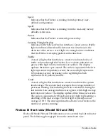
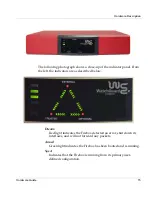
Страница 17: ...icator panel The following photograph shows the entire front view The photograph below shows a close up of the indicator panel From the left the indicators are as described on the next page Disarm Red...

Страница 18: ...ee times per second The scale is exponential the first light represents 64 packets second the second light represents 128 packets second increasing to the eighth light which represents 8 192 packets s...

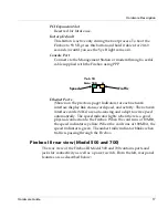
Страница 19: ...rs are as described below Disarm Red light indicates the Firebox detected an error shut down its interfaces and will not forward any packets Armed Green light indicates the Firebox has been booted and...

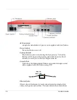
Страница 20: ...es in the direction of the arrows A red light at a triangle corner indicates that the Firebox is denying packets at that interface Firebox III rear view all models except Model 500 and 700 The rear vi...

Страница 21: ...ace display link status card speed and activity The network interface cards NICs are auto sensing and adapt to wire speed automatically The speed indicator lights when there is a good physical connect...

Страница 22: ...ot the Firebox to SYS B press this button and hold it down for 20 60 seconds or until you see the Sys B light come on Console Port Connects to the Management Station or modem through a serial cable su...

Страница 23: ...al specifications All models except Model 500 and 700 Three RJ 45 10 100Tx Ethernet interfaces 1 DB 9 serial port PCI expansion option 500 MHz AMD K6 III processor 300 MHz AMD K6 II processor model 10...

Страница 24: ...ixed baseline set of functionality stored on the read only system area of the Firebox flash disk memory It is possible to start the Firebox using this read only system area when the primary user area...

Страница 25: ...read only system area use one of two methods to initialize the Firebox and prepare it for configuration Factory default switch on back Out of band using a modem Direct using a serial cable However do...

Страница 26: ...face either over the network TCP IP or via a modem using out of band management 4 Click Yes The Connect To Firebox dialog box appears 5 Use the Firebox drop list to select a Firebox or type the IP add...

Страница 27: ...Restore Backup Image Click Continue A verification prompt appears Verify that the Management Station connects to the Firebox Trusted interface either over the network TCP IP or via a modem using out o...

Страница 28: ...24 Hardware Guide...

Страница 29: ...irebox III booting 17 18 cabling using TCP IP 9 front panel 13 15 hardware connections for 8 hardware description 12 hardware requirements 7 initializing using remote provisioning 10 installation 7 in...

Страница 30: ...ng 11 described 14 provisioning remote 10 Q QuickSetup Wizard automatic startup 12 described 11 starting manually 12 R read only system area 20 21 remote provisioning and Process Load Indicator 11 and...

Отзывы: