


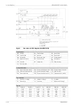


Sensors and indicators:
Engine phase secondary
ST197S
FO leakage clean primary A/B bank
LS103A/B
FO leakage clean secondary A/B bank
LS106A/B
Electrical instruments:
Timing rack position (in actuator)
GT178
Fuel rack control
CV161
Timing rack control
CV178
Pilot fuel pressure control
CV124
Pilot injection valve, cyl A01...A0#
CV1013A...CV10#3A
Pilot injection valve, cyl B01...B0#
CV1013B...CV10#3B
Electric motor
M792
Main fuel oil can be Marine Diesel Fuel (MDF) or Heavy Fuel Oil (HFO). Pilot fuel oil is always
MDF and the pilot fuel system is in operation in both gas and diesel mode operation.
A pressure control valve in the main fuel oil return line on the engine maintains desired pressure
before the high pressure pump.
6.4.1.1
Leak fuel system
Main clean leak fuel from the injection valves and the injection pumps is collected on the
engine and drained by gravity through a clean leak fuel connection (103).
Pilot fuel max outlet pressure: See technical data
The clean leak fuel can be re-used without separation treatment whenever LFO and HFO
doesn’t mix together.
6.4.2
External fuel oil system
External pilot fuel circuit shall be separated from main fuel circuit, if using HFO as main fuel.
The design of the external fuel system may vary from ship to ship, but every system should
provide well cleaned fuel of correct viscosity and pressure to each engine. Temperature control
is required to maintain stable and correct viscosity of the fuel before the injection pumps (see
Technical data). Sufficient circulation through every engine connected to the same circuit must
be ensured in all operating conditions.
The fuel treatment system should comprise at least one settling tank and two separators.
Correct dimensioning of HFO separators is of greatest importance, and therefore the
recommendations of the separator manufacturer must be closely followed. Poorly centrifuged
fuel is harmful to the engine and a high content of water may also damage the fuel feed system.
Injection pumps generate pressure pulses into the fuel feed and return piping.
The fuel pipes between the feed unit and the engine must be properly clamped to rigid
structures. The distance between the fixing points should be at close distance next to the
engine. See chapter Piping design, treatment and installation.
A connection for compressed air should be provided before the engine, together with a drain
from the fuel return line to the clean leakage fuel or overflow tank. With this arrangement it is
possible to blow out fuel from the engine prior to maintenance work, to avoid spilling.
DBAD209883
6-25
6. Fuel System
Wärtsilä 46DF Product Guide
Содержание 46DF
Страница 1: ...W rtsil 46DF PRODUCT GUIDE...
Страница 4: ...This page intentionally left blank...
Страница 8: ...This page intentionally left blank...
Страница 16: ...This page intentionally left blank...
Страница 59: ...Fig 4 3 Cross section of the V engine DBAD209883 4 7 4 Description of the Engine W rtsil 46DF Product Guide...
Страница 118: ...This page intentionally left blank...
Страница 140: ...This page intentionally left blank...
Страница 148: ...This page intentionally left blank...
Страница 154: ...Fig 9 4 V46DF engine driven HT and LT pump 9 6 DBAD209883 W rtsil 46DF Product Guide 9 Cooling Water System...
Страница 174: ...This page intentionally left blank...
Страница 186: ...This page intentionally left blank...
Страница 198: ...This page intentionally left blank...
Страница 206: ...This page intentionally left blank...
Страница 214: ...This page intentionally left blank...
Страница 218: ...This page intentionally left blank...
Страница 230: ...This page intentionally left blank...
Страница 234: ...This page intentionally left blank...
Страница 236: ...This page intentionally left blank...
Страница 241: ...Fig 21 7 List of symbols DAAF406507 7 DBAD209883 21 5 21 ANNEX W rtsil 46DF Product Guide...


