WÄRTSILÄ 46DF Скачать руководство пользователя страница 238

21.2

Collection of drawing symbols used in drawings

Fig 21-1

List of symbols (DAAF406507 - 1)

Fig 21-2

List of symbols (DAAF406507 - 2)

21-2

DBAD209883

Wärtsilä 46DF Product Guide

21. ANNEX

Содержание 46DF

Страница 1: ...W rtsil 46DF PRODUCT GUIDE...

Страница 2: ...MPLICATED TECHNICAL MATTERS SUITED ONLY FOR SPECIALISTS IN THE AREA AND THE DESIGN OF THE SUBJECT PRODUCTS IS SUBJECT TO REGULAR IMPROVEMENTS MODIFICATIONS AND CHANGES CONSEQUENTLY THE PUBLISHER AND C...

Страница 3: ...9 issue replaces all previous issues of the W rtsil 46DF Project Guides Updates Published Issue Many updates changes to the whole Product Guide 13 05 2019 1 2019 New front and backcovers for pdf versi...

Страница 4: ...This page intentionally left blank...

Страница 5: ...ons 4 1 4 2 Main components and systems 4 6 4 3 Cross section of the engine 4 8 4 4 Overhaul intervals and expected life times 4 8 4 5 Engine storage 5 1 5 Piping Design Treatment and Installation 5 1...

Страница 6: ...1 14 Automation System 14 1 14 1 Technical data and system overview 14 3 14 2 Functions 14 7 14 3 Alarm and monitoring signals 14 7 14 4 Electrical consumers 14 9 14 5 Guideline for electrical and aut...

Страница 7: ...1 Lifting of engines 19 2 19 2 Engine components 20 1 20 Product Guide Attachments 21 1 21 ANNEX 21 1 21 1 Unit conversion tables 21 2 21 2 Collection of drawing symbols used in drawings DBAD209883 v...

Страница 8: ...This page intentionally left blank...

Страница 9: ...ounter clockwise on request Direction of rotation 600 rpm Speed 11 6 m s Mean piston speed 1 1 Maximum continuous output Table 1 1 Maximum continuous output IMO Tier 2 Cylinder configuration bhp kW 93...

Страница 10: ...umber Calculation Formulas for different compression ratios if MN 80 and tbax 45 KKNOCK 1 CR 12 7 1 if MN 80 and or tbax 45 KKNOCK 1 0 017 80 MN 1 1 0 01 45 tbax NOTE In case of MN 80 and MN 70 derati...

Страница 11: ...air coolant temperature at rated load CAC Team to be involved for LT water temperature info 6 Glycol usage in cooling water according to document DAAE062266 7 Min suction air temperature is 5 C 8 High...

Страница 12: ...water kg dry air 4 Fuel gas feed pressure is not allowed to decrease from the level given for 36 MJ Nm3 with LHV higher than 36 MJ Nm3 5 Gas fuel lower heating value refers to the gas quality at the e...

Страница 13: ...The statement applies to engines operating in ambient conditions according to ISO 15550 2002 E 100 kPa total barometric pressure 25 C air temperature 30 relative humidity 25 C charge air coolant tempe...

Страница 14: ...WE2 WE1 HE6 HE5 HE4 Engine 102 330 1780 1480 1940 3185 650 2605 650 6L46DF 118 330 1780 1480 1940 3185 650 2605 650 7L46DF 130 398 1780 1480 1940 3185 755 2605 650 8L46DF 146 398 1780 1480 1940 3185...

Страница 15: ...3225 1820 2290 4555 650 3020 800 12V46DF 184 781 3225 1820 2290 4555 650 3020 800 12V46DF 223 781 3225 1820 2290 4555 650 3020 800 14V46DF 235 858 3225 1820 2290 5174 750 3110 800 16V46DF Turbocharge...

Страница 16: ...This page intentionally left blank...

Страница 17: ...rve if necessary Engine load is determined from measured shaft power and actual engine speed The shaft power meter is supplied by W rtsil The propeller efficiency is highest at design pitch It is comm...

Страница 18: ...as the default loading rate for both diesel and gas mode If the control system has only one load increase ramp then the ramp for a preheated engine must be used The HT water temperature in a preheated...

Страница 19: ...ding rate in gas mode it only acts on deviation from reference speed If the loading rate is faster than the capacity in gas mode the engine trips to diesel Electric generators must be capable of 10 ov...

Страница 20: ...rate limitation Fig 2 3 Maximum Loading and Unloading capacity in gas 2 2 2 1 Maximum instant load steps The electrical system must be designed so that tripping of breakers can be safely handled This...

Страница 21: ...10 Maximum speed drop 10 Recovery time 10 s Recovery time 10 s Time between load steps 20 s Time between load steps 20 s Diesel Mode Stepwise Load Reduction Instant Load Application Instant load step...

Страница 22: ...the engine must be loaded to minimum 70 of rated output for 1 hour before transfer to gas Before operating below 10 in gas mode the engine must run above 10 load for at least 10 minutes It is however...

Страница 23: ...operation can be set based on a detailed analysis of project specific conditions such as operational profile fuel composition and engine type and tuning In low load gas operation the oxidation of unb...

Страница 24: ...engine room Engines can run in colder conditions at high loads suction air lower than 5 C provided that special provisions are considered to prevent too low HT water temperature and T C surge For sta...

Страница 25: ...re after air cooler nom TE 601 Exhaust gas system Note 2 13 4 11 0 13 7 11 0 13 7 11 0 kg s Flow at 100 load 11 5 8 4 11 6 8 4 10 7 8 5 kg s Flow at 75 load 314 365 301 367 301 367 C Temperature after...

Страница 26: ...C at 75 load HFO 203 203 197 g kWh SFOC at 50 load HFO Fuel gas system Note 5 600 800 600 800 600 800 kPa a Gas pressure at engine inlet min PT901 at 100 load 120 120 120 kPa a Pressure drop over the...

Страница 27: ...rankcase ventilation flow rate at full load 17 8 17 8 17 8 m3 Crankcase volume 0 5 0 5 0 5 kPa Crankcase ventilation backpressure max 8 5 9 5 8 5 9 5 8 5 9 5 l Oil volume in turning device 1 7 1 7 1 7...

Страница 28: ...s ambient air temperature 25 C and 100 load Tolerance for cooling water heat 10 tolerance for radiation heat 30 Fouling factors and a margin to be taken into account when dimensioning heat exchangers...

Страница 29: ...971 915 969 917 969 917 mm Calculated exhaust diameter for 35 m s Heat balance at 100 load Note 3 1246 980 1260 980 1260 980 kW Jacket water HT circuit 2191 1617 2352 1617 2352 1617 kW Charge air HT c...

Страница 30: ...TE 101 2 0 2 0 2 0 cSt MDF viscosity min 40 40 40 C Max MDF temperature before engine TE 101 5 2 5 2 5 2 kg h Leak fuel quantity HFO clean fuel at 100 load 26 5 14 0 26 5 14 0 26 5 14 0 kg h Leak fue...

Страница 31: ...401 at 100 nom 97 93 97 93 97 93 C Temperature after charge air cooler TE432 150 150 150 m3 h Capacity of engine driven pump nom 100 100 100 kPa Pressure drop over jacket total 100 100 100 kPa Pressu...

Страница 32: ...olerance 5 The fuel consumption at 85 load is guaranteed and the values at other loads are given for indication only Note 4 Consumption values in constant speed are valid for D2 E2 IMO cycles If SCR w...

Страница 33: ...Calculated exhaust diameter for 35 m s Heat balance at 100 load Note 3 1424 1120 1440 1120 1440 1120 kW Jacket water HT circuit 2504 1848 2688 1848 2688 1848 kW Charge air HT circuit 1144 848 1176 84...

Страница 34: ...TE 101 2 0 2 0 2 0 cSt MDF viscosity min 40 40 40 C Max MDF temperature before engine TE 101 6 0 6 0 6 0 kg h Leak fuel quantity HFO clean fuel at 100 load 30 0 16 0 30 0 16 0 30 0 16 0 kg h Leak fuel...

Страница 35: ...401 at 100 nom 97 93 97 93 97 93 C Temperature after charge air cooler TE432 180 180 180 m3 h Capacity of engine driven pump nom 100 100 100 kPa Pressure drop over jacket total 100 100 100 kPa Pressur...

Страница 36: ...olerance 5 The fuel consumption at 85 load is guaranteed and the values at other loads are given for indication only Note 4 Consumption values in constant speed are valid for D2 E2 IMO cycles If SCR w...

Страница 37: ...mm Calculated exhaust diameter for 35 m s Heat balance at 100 load Note 3 1602 1260 1620 1260 1620 1260 kW Jacket water HT circuit 2817 2079 3024 2079 3024 2079 kW Charge air HT circuit 1287 954 1323...

Страница 38: ...101 2 0 2 0 2 0 cSt MDF viscosity min 40 40 40 C Max MDF temperature before engine TE 101 6 75 6 75 6 75 kg h Leak fuel quantity HFO clean fuel at 100 load 33 75 18 0 33 75 18 0 33 75 18 0 kg h Leak f...

Страница 39: ...E 401 at 100 nom 97 93 97 93 97 93 C Temperature after charge air cooler TE432 180 180 180 m3 h Capacity of engine driven pump nom 100 100 100 kPa Pressure drop over jacket total 100 100 100 kPa Press...

Страница 40: ...olerance 5 The fuel consumption at 85 load is guaranteed and the values at other loads are given for indication only Note 4 Consumption values in constant speed are valid for D2 E2 IMO cycles If SCR w...

Страница 41: ...200 1269 1200 mm Calculated exhaust diameter for 35 m s Heat balance at 100 load Note 3 2136 1680 2160 1680 2160 1680 kW Jacket water HT circuit 3756 2772 4032 2772 4032 2772 kW Charge air HT circuit...

Страница 42: ...ine TE 101 2 0 2 0 2 0 cSt MDF viscosity min 40 40 40 C Max MDF temperature before engine TE 101 9 0 9 0 9 0 kg h Leak fuel quantity HFO clean fuel at 100 load 45 0 24 0 45 0 24 0 45 0 24 0 kg h Leak...

Страница 43: ...TE 401 at 100 nom 97 93 97 93 97 93 C Temperature after charge air cooler TE432 240 240 240 m3 h Capacity of engine driven pump nom 100 100 100 kPa Pressure drop over jacket total 100 100 100 kPa Pre...

Страница 44: ...olerance 5 The fuel consumption at 85 load is guaranteed and the values at other loads are given for indication only Note 4 Consumption values in constant speed are valid for D2 E2 IMO cycles If SCR w...

Страница 45: ...96 1370 1296 mm Calculated exhaust diameter for 35 m s Heat balance at 100 load Note 3 2492 1960 2520 1960 2520 1960 kW Jacket water HT circuit 4382 3234 4704 3234 4704 3234 kW Charge air HT circuit 2...

Страница 46: ...e TE 101 2 0 2 0 2 0 cSt MDF viscosity min 45 45 45 C Max MDF temperature before engine TE 101 10 5 10 5 10 5 kg h Leak fuel quantity HFO clean fuel at 100 load 53 0 32 0 53 0 32 0 53 0 32 0 kg h Leak...

Страница 47: ...TE 401 at 100 nom 97 93 97 93 97 93 C Temperature after charge air cooler TE432 280 280 280 m3 h Capacity of engine driven pump nom 100 100 100 kPa Pressure drop over jacket total 100 100 100 kPa Pre...

Страница 48: ...olerance 5 The fuel consumption at 85 load is guaranteed and the values at other loads are given for indication only Note 4 Consumption values in constant speed are valid for D2 E2 IMO cycles If SCR w...

Страница 49: ...1465 1386 mm Calculated exhaust diameter for 35 m s Heat balance at 100 load Note 3 2848 2240 2880 2240 2880 2240 kW Jacket water HT circuit 5008 3696 5376 3696 5376 3696 kW Charge air HT circuit 228...

Страница 50: ...ngine TE 101 2 0 2 0 2 0 cSt MDF viscosity min 40 40 40 C Max MDF temperature before engine TE 101 12 0 12 0 12 0 kg h Leak fuel quantity HFO clean fuel at 100 load 60 0 36 0 60 0 36 0 60 0 36 0 kg h...

Страница 51: ...401 at 100 nom 97 93 97 93 97 93 C Temperature after charge air cooler TE432 340 340 340 m3 h Capacity of engine driven pump nom 100 100 100 kPa Pressure drop over jacket total 100 100 100 kPa Pressu...

Страница 52: ...olerance 5 The fuel consumption at 85 load is guaranteed and the values at other loads are given for indication only Note 4 Consumption values in constant speed are valid for D2 E2 IMO cycles If SCR w...

Страница 53: ...for the camshaft drive and flywheel The bearing housing of the intermediate gear is integrated in the engine block The cooling water is distributed around the cylinder liners with water distribution...

Страница 54: ...imum running conditions for the piston and piston rings The liner material is a special grey cast iron alloy developed for excellent wear resistance and high strength Accurate temperature control is a...

Страница 55: ...cylinder are electronically controlled and actuated to feed each individual cylinder with the correct amount of gas The gas admission valves are controlled by the engine control system to regulate eng...

Страница 56: ...re pulses The high pressure piping is of double wall shielded type and well protected inside the hot box The feed pipes distribute the pilot fuel from the common rail to the injection valves The pilot...

Страница 57: ...rtsil 46DF is equipped with a modular embedded automation system W rtsil Unified Controls UNIC The UNIC system have hardwired interface for control functions and a bus communication interface for alar...

Страница 58: ...4 3 Cross section of the engine Fig 4 2 Cross section of the in line engine 4 6 DBAD209883 W rtsil 46DF Product Guide 4 Description of the Engine...

Страница 59: ...Fig 4 3 Cross section of the V engine DBAD209883 4 7 4 Description of the Engine W rtsil 46DF Product Guide...

Страница 60: ...0 20000 Cylinder head 180000 16000 180000 24000 Cylinder liner 12000 18000 12000 18000 36000 12000 18000 Exhaust valve 32000 8000 Inj valve complete 8000 8000 8000 8000 Injection nozzles 24000 12000 H...

Страница 61: ...ken into consideration Pockets shall be avoided When not possible drain plugs and air vents shall be installed Leak fuel drain pipes shall have continuous slope Vent pipes shall be continuously rising...

Страница 62: ...on will take place particularly if air is not dry Even these velocities can be high in terms of their effect on pressure drop In longer supply lines it is often necessary to restrict velocities to 15...

Страница 63: ...MPa 4 bar The highest point of the pump curve at or near zero flow is 0 1 MPa 1 bar higher than the nominal point and consequently the discharge pressure may rise to 0 5 MPa 5 bar with closed or thro...

Страница 64: ...curs i e before and after heat exchangers etc Pressure gauges should be installed on the suction and discharge side of each pump 5 7 Cleaning procedures Instructions shall be given at an early stage t...

Страница 65: ...used should be protected by a suction strainer During this time the welds in the fuel piping should be gently knocked at with a hammer to release slag and the filter inspected and carefully cleaned a...

Страница 66: ...id and welded to the steel structure of the foundation to prevent vibrations and external forces to the connection which could damage the flexible connections and transmit noise The support must be cl...

Страница 67: ...Fig 5 1 Flexible hoses Drawing V60L0796 below is showing how pipes shall be clamped DBAD209883 5 7 5 Piping Design Treatment and Installation W rtsil 46DF Product Guide...

Страница 68: ...as possible to the flexible connection Next support should be 0 3 0 5 m from the first support First three supports closest to the engine or generating set should be fixed supports Where necessary sli...

Страница 69: ...Fig 5 3 Flange supports of flexible pipe connections 4V60L0796 DBAD209883 5 9 5 Piping Design Treatment and Installation W rtsil 46DF Product Guide...

Страница 70: ...Fig 5 4 Pipe clamp for fixed support V61H0842A 5 10 DBAD209883 W rtsil 46DF Product Guide 5 Piping Design Treatment and Installation...

Страница 71: ...nock testing engine The Methane Number MN gives a scale for evaluation of the resistance to knock of gaseous fuels 3 To define the Methane Number MN of the gas the method included in the EN 16726 2015...

Страница 72: ...ompared to DMA category fuels but a presence of max 7 0 v v of Fatty acid methyl ester FAME is allowed DMZ A high quality distillate generally designated MGO Marine Gas Oil in the marine field An alte...

Страница 73: ...D7963 or IP 579 7 0 7 0 7 0 Max v v Fatty acid methyl ester FAME e ISO 10370 0 30 0 30 0 30 Max m m Carbon residue Micro meth od On 10 distillation residue ISO 10370 0 30 Max m m Carbon residue Micro...

Страница 74: ...filled k There doesn t exist any minimum sulphur content limit for W rtsil DF engines and also the use of Ultra Low Sulphur Diesel ULSD is allowed provided that the fuel quality fulfils other specifie...

Страница 75: ...matic viscosity before fuel pumps Limit Unit Characteristics mm s a 2 0 Kinematic viscosity before pilot fuel pump min 11 0 Kinematic viscosity before pilot fuel pump max mm s a 2 0 Kinematic viscosit...

Страница 76: ...Kinematic viscosity bef injection pumps c ISO 3104 80 00 30 00 10 00 mm2 s a Kinematic viscosity at 50 C max ISO 3675 or ISO 12185 975 0 960 0 920 0 kg m3 Density at 15 C max ISO 8217 Annex F 860 860...

Страница 77: ...ine fuels ignition properties especially concerning fuels originating from modern and more complex refinery processes f Sodium contributes to hot corrosion on exhaust valves when combined with high su...

Страница 78: ...10 0 a 991 0 1010 0 a kg m3 Density at 15 C max ISO 8217 870 850 CCAI max f ISO 8754 or ISO 14596 Statutory require ments but max 4 50 m m m m Sulphur max c g ISO 2719 60 0 60 0 C Flash point min IP 5...

Страница 79: ...pecially concerning fuels originating from modern and more complex refinery processes g Sodium contributes to hot corrosion on exhaust valves when combined with high sulphur and vanadium contents Sodi...

Страница 80: ...de 6 2 2 Diesel mode operation In diesel operating mode the engine operates only on liquid fuel oil MDF or HFO is used as fuel with a conventional fuel injection system The MDF pilot injection is alwa...

Страница 81: ...her situations The on engine MCC De gassing valve releases the gas pressure from the on engine pipe and from the external branch between engine and external GVU gas pressure control valve to a safe ex...

Страница 82: ...to double wall gas system 726 Sensors and indicators Main gas pressure PT901 Knock cyl A01 A0 SE614A SE60 4A MCC de gassing valve 1 position open GS9470 1 Cylinder pressure cyl A01 A0 PT5011A PT50 4A...

Страница 83: ...closed GS947C 1 Cylinder pressure cyl B01 B0 PT5011B PT50 4B MCC de gassing valve 2 position open GS9470 2 Main gas valve control cyl A01 A0 CV9011A CV90 1A MCC de gassing valve 2 position closed GS9...

Страница 84: ...of gas system Other venting valves are placed in the external gas system MCC de gassing valve is on engine at end of gas manifold Line engines have internally one MCC de gassing valve Vee engines hav...

Страница 85: ...with double wall gas pipes A Gas Valve Unit GVU is required for each engine and has to be located as close the engine as possible Fig 6 4 Gas supply system with the Gas Valve Unit GVU and the main com...

Страница 86: ...valve unit 10N05 Flexible pipe connections for DF engines 10H01 Fig 6 6 External fuel gas system GVU without enclouse with cabinet DAAF366890 Pipe connections System components Gas inlet 108 Gas detec...

Страница 87: ...nnections System components Gas inlet 108 Gas detector 03 Safety ventilation 708 Gas double wall system ventilation fan 04 Air inlet to double wall gas system 726 Gas valve unit 10N05 Flexible pipe co...

Страница 88: ...The ventilation air is taken from both inlets and lead through the annular space of the double wall pipe to the GVU room or to the enclosure of the gas valve unit From the enclosure of the gas valve...

Страница 89: ...he pressure trapped between the block valves after closing of the block valves The block valves V03 and V05 and inert gas valve V07 are operated as fail to close i e they will close on current failure...

Страница 90: ...4 Pressure transmitter gas inlet PT01 Mass flow meter FT01 Pressure transmitter inert gas PT05 Pressure manometer gas inlet PI02 Temperature sensor gas inlet TE01 Pressure transmitter control air PT06...

Страница 91: ...engine during maintenance vent lines from gas supply or GVU of different engines cannot be interconnected However vent lines from the same engine can be interconnected to a common header which shall...

Страница 92: ...see section Technical Data and chapter 1 3 2 Output limitations due to gas feed pressure and lower heating value For pressure requirements see chapters Technical Data and Output limitations due to met...

Страница 93: ...er in stop position GS171 Pilot fuel press pump outlet PT125 Turning gear engaged GS792 Pilot fuel filter pressure difference PDS129 Fuel oil press engine inlet PT101 Engine speed primary ST196P ST173...

Страница 94: ...bank 102 A B Leak fuel drain dirty fuel B bank DE 104BD Leak fuel drain clean fuel A bank DE 103AD Pilot fuel inlet 112 Leak fuel drain clean fuel B bank DE 103BD Pilot fuel outlet 117 Leak fuel drain...

Страница 95: ...external fuel system may vary from ship to ship but every system should provide well cleaned fuel of correct viscosity and pressure to each engine Temperature control is required to maintain stable an...

Страница 96: ...ability especially when comparing different suppliers Typically a totally different value than XX micron absolute e g a real example 10 micron nominal e10 60 approx 60 micron absolute XX micron absolu...

Страница 97: ...nt in parallel to the nearest viscosity temperature line in the diagram Example 2 Known viscosity 60 cSt at 50 C K The following can be read along the dotted line viscosity at 80 C 20 cSt temperature...

Страница 98: ...mps If black out starting with MDF from a gravity tank is foreseen then the tank must be located at least 15 m above the engine crankshaft Leak fuel tank clean fuel 1T04 Clean leak fuel is drained by...

Страница 99: ...ls with densities exceeding 991 kg m3 at 15 C In this case the main and stand by separators should be run in parallel When separators with gravity disc are used then each stand by separator should be...

Страница 100: ...or feed pumps 1P02 Feed pumps should be dimensioned for the actual fuel quality and recommended throughput of the separator The pump should be protected by a suction strainer mesh size about 0 5 mm An...

Страница 101: ...in heater C T For heavy fuels T 48 C can be used i e a settling tank temperature of 50 C Fuels having a viscosity higher than 5 cSt at 50 C require pre heating before the separator The heaters to be...

Страница 102: ...nk 1T05 The sludge tank should be located directly beneath the separators or as close as possible below the separators unless it is integrated in the separator unit The sludge pipe must be continuousl...

Страница 103: ...uick closing valve fuel oil tank 1V10 Flow meter MDF 1I03 Flexible pipe connection 1HX0 Pipe connections Leak fuel drain dirty fuel 104 Fuel inlet 101 Pilot fuel inlet 112 Fuel outlet 102 Pilot fuel o...

Страница 104: ...low meter MDF 1I03 Pipe connections Leak fuel drain dirty fuel 104 Fuel inlet 101 Pilot fuel inlet 112 Fuel outlet 102 Pilot fuel outlet 117 Leak fuel drain clean fuel 103 Fig 6 16 Example of fuel fee...

Страница 105: ...w valve HFO MDF 1V05 Pilot fuel fine filter MDF 1F10 Quick closing valve fuel oil tank 1V10 Flow meter MDF 1I03 Pipe connections Leak fuel drain dirty fuel 104 Fuel inlet 101 Pilot fuel inlet 112 Fuel...

Страница 106: ...ad of the day tank one consumption meter is sufficient for monitoring of the fuel consumption provided that the meter is installed in the feed line from the day tank before the return fuel tank A fuel...

Страница 107: ...data 4 5 kW cyl at full load Heat to be dissipated 80 kPa 0 8 bar Max pressure drop fuel oil 60 kPa 0 6 bar Max pressure drop water min 15 Margin heat rate fouling 50 150 C Design temperature MDF HFO...

Страница 108: ...FO 1F03 Pressure control valve MDF 1V02 Suction filter booster unit 1F06 Pressure control valve booster unit 1V03 Automatic filter booster unit 1F08 Venting valve booster unit 1V07 Pilot fuel fine fil...

Страница 109: ...ty filter HFO 1F03 Change over valve 1V01 Suction filter booster unit 1F06 Pressure control valve booster unit 1V03 Automatic filter booster unit 1F08 Overflow valve HFO MDF 1V05 Pilot fuel fine filte...

Страница 110: ...ump MDF 1P13 Cooler booster unit 1E03 Day tank HFO 1T03 Cooler MDF 1E04 Day tank MDF 1T06 Safety filter HFO 1F03 De aeration tank booster unit 1T08 Suction filter booster unit 1F06 Change over valve 1...

Страница 111: ...fore switching over to the MDF circulating pumps As mentioned earlier sustained operation on MDF usually requires a fuel oil cooler The viscosity at the engine shall not drop below the minimum limit s...

Страница 112: ...ith by pass filter One viscosimeter for control of the heaters One control valve for steam or thermal oil heaters a control cabinet for electric heaters One temperature sensor for emergency control of...

Страница 113: ...in the de aeration tank by directing the surplus flow to the suction side of the feed pump Design data Equal to feed pump Capacity 1 6 MPa 16 bar Design pressure 100 C Design temperature 0 3 0 5 MPa 3...

Страница 114: ...pump is to circulate the fuel in the system and to maintain the required pressure at the injection pumps for single engine circuit or before circulation pumps 1P12 for multi engines circuit Pressure i...

Страница 115: ...osimeter should be of a design that can withstand the pressure peaks caused by the injection pumps of the diesel engine Design data 0 50 cSt Operating range 180 C Design temperature 4 MPa 40 bar Desig...

Страница 116: ...e dimensioned to secure a stable pressure over the whole operating range Design data Equal to circulation pump 1P06 Capacity 1 6 MPa 16 bar Design pressure 150 C Design temperature 0 2 0 7 MPa 2 7 bar...

Страница 117: ...ation of a temporary flushing filter The fuel pipes at the engine connections 101 and 102 are disconnected and the supply and return lines are connected with a temporary pipe or hose on the installati...

Страница 118: ...This page intentionally left blank...

Страница 119: ...5 30 55 GRADE NO 4D GRADE NO 5 6 ASTM D 975 01 ASTM D 396 04 C DMC RMA10 RMK55 BS MA 100 1996 DC A30 K700 CIMAC 2003 RMA10 RMK700 ISO 8217 2017 E In installation where engines are running periodicall...

Страница 120: ...E 40 is acceptable in normal operating conditions Usually the same oil as in the engine can be used At low ambient temperatures it may be necessary to use a multigrade oil e g SAE 5W 40 to ensure prop...

Страница 121: ...C valve PT291A LO press engine inlet PT201 LO temp TC A outlet TE272 LO press engine inlet PTZ201 Crankcase pressure PT700 LO temperature LOC inlet TE231 Speed balancing system monitoring ST199 LO tem...

Страница 122: ...7L and 9L Option on 6L and 8L with TFRS Sensors and indicators Control oil pressure after VIC valve A B bank PT291A B LO press engine inlet PT201 LO temp TC A outlet TE272 LO press engine inlet PTZ201...

Страница 123: ...19 Lube oil outlet from oil sump free end A B bank 202 AF BF Flushing oil from automatic filter 223 Lube oil to engine driven pump 203 Crankcase air vent 701A B Lubre oil from priming pump 206 Alterna...

Страница 124: ...oil pump is of screw type and is equipped with a pressure control valve Concerning suction height flow rate and pressure of the engine driven pump see Technical Data All engines are delivered with a r...

Страница 125: ...or unit 2S01 Suction strainer main lube oil pump 2F01 Condensate trap 2S02 Suction filter separator unit 2F03 System oil tank 2T01 Suction strainer prelube oil pump 2F04 Sludge tank 2T06 Suction filte...

Страница 126: ...strainer main lube oil pump 2F01 Condensate trap 2S02 Suction filter separator unit 2F03 System oil tank 2T01 Suction strainer prelube oil pump 2F04 Sludge tank 2T06 Suction filter stand by pump 2F06...

Страница 127: ...densate trap 2S02 Suction strainer main lube oil pump 2F01 System oil tank 2T01 Suction filter separator unit 2F03 Sludge tank 2T06 Suction strainer prelube oil pump 2F04 Flexible pipe connections 2HX...

Страница 128: ...nsate trap 2S02 Suction strainer main lube oil pump 2F01 System oil tank 2T01 Suction filter separator unit 2F03 Sludge tank 2T06 Suction strainer prelube oil pump 2F04 Flexible pipe connections 2H0X...

Страница 129: ...Automatic filter LO 2F02 Condensate trap 2S02 Suction filter separator unit 2F03 System oil tank 2T01 Suction strainer prelube oil pump 2F04 Sludge tank 2T06 Safety filter LO 2F05 Flexible pipe conne...

Страница 130: ...utomatic filter LO 2F02 Condensate trap 2S02 Suction filter separator unit 2F03 System oil tank 2T01 Suction strainer prelube oil pump 2F04 Sludge tank 2T06 Safety filter LO 2F05 Flexible pipe connect...

Страница 131: ...the system oil tank When the engine is running the temperature in the system oil tank located in the ship s bottom is normally 65 75 C To enable separation with a stopped engine the heater capacity mu...

Страница 132: ...mum oil level in the tank Further on the return pipes must not be located in the same corner of the tank as the suction pipe of the pump The suction pipe of the pump should have a trumpet shaped or co...

Страница 133: ...ion strainers 2F01 2F04 2F06 It is recommended to install a suction strainer before each pump to protect the pump from damage The suction strainer and the suction pipe must be amply dimensioned to min...

Страница 134: ...h a safety valve The installation of a pre lubricating pump is mandatory An electrically driven main pump or standby pump with full pressure may not be used instead of a dedicated pre lubricating pump...

Страница 135: ...re drop water 49 C Water temperature before cooler 56 C Oil temperature before engine 1 0 MPa 10 bar Design pressure min 15 Margin heat rate fouling Fig 7 10 Main dimensions of the lubricating oil coo...

Страница 136: ...c filter 2F02 When off engine main filter it is recommended to select an automatic filter with an insert filter in the bypass line thus enabling easy changeover to the insert filter during maintenance...

Страница 137: ...hese models have a simple pressure regulating valve afterwards Backflush filter sludge oil must be discharged to sludge tank when no further post filtration occurs To be re used it must be filtered by...

Страница 138: ...hose from crankcase ventilation outlet extra mass on the oil mist detector must be avoided There should be a fixing point on both sides of the pipe at the support Absolutely rigid mounting between th...

Страница 139: ...bout 65 C or by using a separate flushing oil which has an ideal viscosity in ambient temperature 7 5 3 2 Flushing with engine oil The ideal is to use engine oil for flushing This requires however tha...

Страница 140: ...This page intentionally left blank...

Страница 141: ...ompressed air system All engines are started by means of compressed air with a nominal pressure of 3 MPa the minimum recommended air pressure is 1 8 MPa The start is performed by direct injection of a...

Страница 142: ...e 40bar 05 Air filter 13 Valve for automatic draining 06 Air container 14 Starting and slow turning valve 07 Instruments Starting air press engine inlet PT301 Stop shutdown solenoid valve 1 CV153 1 Co...

Страница 143: ...nders 11 Starting air distributor 04 Oil mist detector 12 Bursting disc break pressure 40 bar 05 Air filter 13 Valve for automatic draining 06 Air container 14 Starting and slow turning valve 07 Senso...

Страница 144: ...ections Starting air inlet 30 bar 301 Control air inlet 30 bar 302 Driving air inlet to oil mist detector 6 8 bar 303 Instrument air inlet 320 8 4 DBAD209883 W rtsil 46DF Product Guide 8 Compressed Ai...

Страница 145: ...yer Fig 8 3 Example of external compressed air system DAAF372066 A Pipe connections System components Starting air inlet 301 Diesel engine WV46DF 01 Control air inlet 302 Diesel engine WV46DF 02 Drivi...

Страница 146: ...els are to be equipped with at least a manual valve for condensate drain If the air vessels are mounted horizontally there must be an inclination of 3 5 towards the drain valve to ensure efficient dra...

Страница 147: ...er starting air inlet 3F02 Condense formation after the water separator between starting air compressor and starting air vessels create and loosen abrasive rust from the piping fittings and receivers...

Страница 148: ...This page intentionally left blank...

Страница 149: ...the engines It is important that water of acceptable quality and approved corrosion inhibitors are used directly when the system is filled after completed installation 9 1 1 Corrosion inhibitors The...

Страница 150: ...mp jacket inlet TE401 HT cooling water thermostat valve control external CV432 Liner temperature 1 cyl A bank TE7011A 1A HT cooling water thermostat valve position external GT432 Liner temperature 2 c...

Страница 151: ...r outlet 402 LT water outlet 452 Water from preheater for HT circuit 406 LT water air vent from CAC 454 HT water from stand by pump 408 LT water from stand by pump 457 HT water drain 411 LT water air...

Страница 152: ...e 1 cyl A bank TE7011A 1A HT cooling water thermostat valve position external GT432 Liner temperature 2 cyl A bank TE7012A 2A HT water temp jacket outlet B bank TE403 Liner temperature 1 cyl B bank TE...

Страница 153: ...1 Engine driven circulating pumps The LT and HT cooling water pumps are usually engine driven In some installations it can however be desirable to have separate LT HT pumps and therefore engines are...

Страница 154: ...Fig 9 4 V46DF engine driven HT and LT pump 9 6 DBAD209883 W rtsil 46DF Product Guide 9 Cooling Water System...

Страница 155: ...inner surfaces are not allowed in the fresh water cooling system Some cooling water additives react with zinc forming harmful sludge Zinc also becomes nobler than iron at elevated temperatures which c...

Страница 156: ...04 DN150 Water from preheater to HT circuit 406 DN150 HT water from stand by pump 408 OD22 HT water drain 411 OD15 HT water air vent from CAC 416 DN150 LT water inlet 451 DN150 LT water outlet 452 OD1...

Страница 157: ...T 4V01 Evaporator unit 4N02 Temp control valve heat recovery 4V02 Transfer pump 4P09 Temp control valve central cooler 4V08 Circulating pump HT 4P14 Temperature control valv charge air 4V09 Circulatin...

Страница 158: ...n engine separeted LT HT DAAF418509 System components Air dearator HT 4S02 Raw water cooler HT 4E04 Air dearator LT 4S03 Heater preheater 4E05 Expansion tank HT 4T01 Raw water cooler LT 4E06 Expansion...

Страница 159: ...pe connections DN150 HT water inlet 401 DN150 HT water outlet 402 OD15 HT water air vent 404 DN150 HT water from preheater to HT circuit 406 DN150 HT water from stand by pump 408 OD22 HT water drain 4...

Страница 160: ...ir vent from CAC 416 DN150 LT water inlet 451 DN150 LT water outlet 452 OD15 LT water air vent from air cooler 454 DN150 LT water from stand by pump 457 LT water air vent 483 System components Air dea...

Страница 161: ...seawater temperature It is recommended to divide the engines into several circuits in multi engine installations One reason is of course redundancy but it is also easier to tune the individual flows i...

Страница 162: ...control valve can be either self actuated or electrically actuated Normally there is one temperature control valve per circuit The set point of the control valve is 35 C or lower if required by other...

Страница 163: ...sign data see chapter Technical Data Fresh water flow see chapter Technical Data Heat to be dissipated max 60 kPa 0 6 bar Pressure drop on fresh water side acc to cooler manufacturer normally 1 2 1 5...

Страница 164: ...by circulation to the expansion tank radiation from piping and leakages in temperature control valves 9 3 9 Air venting Air may be entrained in the system after an overhaul or a leak may continuously...

Страница 165: ...the total system volume Volume NOTE The maximum pressure at the engine must not be exceeded in case an electrically driven pump is installed significantly higher than the engine Concerning the water...

Страница 166: ...vent pipes The table below can be used for guidance Table 9 1 Minimum diameter of balance pipe Max number of vent pipes with 5 mm ori fice Max flow velocity m s Nominal pipe size 6 1 2 DN 40 10 1 3 D...

Страница 167: ...gas Min 70 C for startings at HFO Preheating temperature 12 kW cyl Required heating power 6 kW cyl Heating power to keep hot engine warm Required heating power to heat up the engine see formula below...

Страница 168: ...2 225 67 900 950 1455 665 81 260 91 900 1000 1445 715 108 260 109 1100 1000 1645 715 135 315 143 1100 1100 1640 765 147 315 142 1100 1100 1640 765 169 375 190 1100 1200 1710 940 203 375 190 1100 1200...

Страница 169: ...0 KVDS 170 200 1260 1190 200 KVDS 200 205 1260 1190 240 KVDS 240 205 1260 1430 270 KVDS 270 9 3 13 Throttles Throttles orifices are to be installed in all by pass lines to ensure balanced operating co...

Страница 170: ...be installed wherever there is a temperature change i e before and after heat exchangers etc in external system Local pressure gauges should be installed on the suction and discharge side of each pump...

Страница 171: ...ed for ventilation note also that the earlier mentioned demand on 30 air exchanges hour has to be fulfilled is then calculated using the formula where qv air flow m s total heat emission to be evacuat...

Страница 172: ...ual control the fan speed can be controlled by engine load In multi engine installations each main engine should preferably have its own combustion air fan Thus the air flow can be adapted to the numb...

Страница 173: ...oolers Example according to the diagram At an ambient air temperature of 35 C and a relative humidity of 80 the content of water in the air is 0 029 kg water kg dry air If the air manifold pressure re...

Страница 174: ...This page intentionally left blank...

Страница 175: ...rol CV519 Exh gas temperature cyl 0 A TE50 1A Exhaust wastegate position GT519 Exh gas temperature TC inlet TE511 Charge air by pass control CV643 Exh gas temperature TC outlet TE517 Charge air by pas...

Страница 176: ...stegate outlet 611 Cleaning water to turbine 502 Scavenging air outlet to TC cleaning valve unit 614 Cleaning water to compressor 509 Condensate after air cooler 607 11 2 DBAD209883 W rtsil 46DF Produ...

Страница 177: ...633 Exh gas temperature TC B inlet TE521 Charge air by pass position GT643 Exh gas temperature TC B outlet TE527 Charge air wastegate control CV656 TC A speed SE518 Charge air wastegate position GT656...

Страница 178: ...iameters and support B mm A mm TC type Engine type DN900 650 A170 W 6L46DF DN1000 650 A170 W 7L46DF DN1000 750 A175 W 8L46DF DN1100 750 A175 W 9L46DF DN1300 650 A170 W 12V46DF DN1400 650 A170 W 14V46D...

Страница 179: ...oper design of the exhaust system the engine will not be damaged and the explosion gases will be safely directed through predefined routes The following guidelines should be observed when designing th...

Страница 180: ...ose to the turbocharger as possible The exhaust gas ventilation sequence is automatically controlled by the GVU Fig 11 6 Exhaust gas ventilation arrangement DAAF315146A Unit components Drain 4 Switch...

Страница 181: ...r the insulation should consist of a hook on padding to facilitate maintenance It is especially important to prevent the airstream to the turbocharger from detaching insulation which will clog the fil...

Страница 182: ...rangement on the engine in order to keep the exhaust gas temperature and backpressure into SCR unit working range The exhaust gas piping must be straight at least 3 5 meters in front of the SCR unit I...

Страница 183: ...ngines Cleaning is started from the control panel on the control unit and the cleaning sequence is then controlled automatically A flow meter and a pressure control valve are supplied for adjustment o...

Страница 184: ...r Air Water Engine 0 80 l min System air for scavening at low load l min Water consump tion wash l Water inlet flow rate l min Nom water inlet press after press contr valve Water inlet press before co...

Страница 185: ...KK4DA X 480 48 4 0 5 0 8 0 2 TPL71 C 12V46DF KK4DA X 740 74 4 0 5 0 8 0 2 TPL76 C 16V46DF DBAD209883 12 3 12 Turbocharger Cleaning W rtsil 46DF Product Guide...

Страница 186: ...This page intentionally left blank...

Страница 187: ...for any ordinary diesel engine and the engine will be delivered with an EIAPP certificate to show compliance with the MARPOL Annex VI 13 2 Marine exhaust emissions legislation 13 2 1 International Ma...

Страница 188: ...ines same methods as mentioned above can be used to reduce exhaust emissions when running in diesel mode In gas mode there is no need for scrubber or SCR Refer to the W rtsil Environmental Product Gui...

Страница 189: ...municated over a Modbus TCP connection to external systems 14 1 Technical data and system overview 14 1 1 Ingress protection The ingress protection class of the system is IP54 14 1 2 Ambient temp for...

Страница 190: ...red on the engine 14 1 3 Local operator panel The Local operator panel LOP consist of a display unit LDU with touch screen and pushbuttons as well as an emergency stop button built on the engine The l...

Страница 191: ...installed in a steel sheet cabinet for bulkhead mounting protection class IP44 14 2 Functions 14 2 1 Engine operating modes The operator can select two different fuel operating modes Gas operating mod...

Страница 192: ...device 14 2 2 2 Start in gas operating mode If the engine is ready to start in gas operating mode the output signals engine ready for gas operation no gas trips are active and engine ready for start n...

Страница 193: ...irst engine is started in backup operating mode connected to switchboard loaded and consequently blackout signal cleared more engines should be started and the one running in backup mode stopped and r...

Страница 194: ...cy stop 14 2 4 1 Stop mode Before stopping the engine the control system shall first unload the engine slowly if the engine is loaded and after that open the generator breaker and send a stop signal t...

Страница 195: ...ng With isochronous load sharing there is no need for load balancing frequency adjustment or generator loading unloading control in the external control system In a speed droop system each individual...

Страница 196: ...oil if applicable 2P04 The engine control system starts the pump automatically via a motor starter if the lubricating oil pressure drops below a preset level when the engine is running There is a dedi...

Страница 197: ...limitation The response to increase and decrease pulses from PMS or synchroniser is 0 1 Hz per second by default but the rate is adjustable This is the rate for the speed setting Actual speed and or...

Страница 198: ...This page intentionally left blank...

Страница 199: ...ide of the engine are to be 46 H7 n6 fitted bolts The rest of the holding down bolts are clearance bolts A distance sleeve should be used together with the fitted bolts The distance sleeve must be mou...

Страница 200: ...should be designed so that the wedge type steel chocks can easily be fitted into their positions The wedge type chocks also have an inclination of 1 100 to match the inclination of the seating If the...

Страница 201: ...g and fastening rigidly mounted in line engine on resin chocks DAAE012078a Fig 15 2 Seating and fastening rigidly mounted V engine on resin chocks DAAE074226A DBAD209883 15 3 15 Foundation W rtsil 46D...

Страница 202: ...Fig 15 3 Seating and fastening rigidly mounted in line engine on resin chocks DAAE012078a 15 4 DBAD209883 W rtsil 46DF Product Guide 15 Foundation...

Страница 203: ...Fig 15 4 Seating and fastening rigidly mounted V engine on resin chocks DAAE074226A DBAD209883 15 5 15 Foundation W rtsil 46DF Product Guide...

Страница 204: ...final alignment adjustments and drilling of the holes for the fastening screws The steel spring elements are compressed to the calculated height under load and locked in position on delivery Compressi...

Страница 205: ...engine Especially the connection to the turbocharger must be arranged so that the above mentioned displacements can be absorbed without large forces on the turbocharger Proper fixing of pipes next to...

Страница 206: ...This page intentionally left blank...

Страница 207: ...uld avoid natural frequencies of decks bulkheads and superstructures close to the excitation frequencies The double bottom should be stiff enough to avoid resonances especially with the rolling freque...

Страница 208: ...re quency Hz Speed rpm Engine 11 40 163 20 30 30 10 600 9L46DF 13 5 40 86 155 20 103 103 10 600 14V46DF 13 5 40 86 155 20 10 600 14V46DF2 1 zero or insignificant value marked as 2 balancing device ado...

Страница 209: ...112 60 35 30 600 12V46DF 2 90 90 60 20 30 600 14V46DF 6 120 63 80 65 40 600 16V46DF 16 3 Mass moments of inertia These typical inertia values include the flexible coupling part connected to the flywhe...

Страница 210: ...16 4 Structure borne noise Fig 16 2 Typical structure borne noise levels 16 4 DBAD209883 W rtsil 46DF Product Guide 16 Vibration and Noise...

Страница 211: ...ke air filter on the turbocharger and 1m from the engine 90 of all measured noise levels are below the values in the graphs The values presented in the graphs below are typical values cylinder specifi...

Страница 212: ...to ISO 9614 2 The results are presented with A weighting in octave bands reference level 1 pW The values presented in the graphs below are typical values cylinder specific graphs are included in the...

Страница 213: ...Fig 16 5 Typical sound power levels of exhaust noise W6L46DF Fig 16 6 Typical sound power levels of exhaust noise W12V46DF DBAD209883 16 7 16 Vibration and Noise W rtsil 46DF Product Guide...

Страница 214: ...This page intentionally left blank...

Страница 215: ...screw vessels which can operate on one shaft line only 17 3 Shaft locking device A shaft locking device should also be fitted to be able to secure the propeller shaft in position so that wind milling...

Страница 216: ...ss of shafts between rotating masses Material of shafts including tensile strength and modulus of rigidity Gear ratios Drawing number of the diagram Propeller and shafting A mass elastic diagram or pr...

Страница 217: ...ed the following data of it must be informed Mass moment of inertia of all parts of the coupling Number of flexible elements Linear progressive or degressive torsional stiffness per element Dynamic ma...

Страница 218: ...This page intentionally left blank...

Страница 219: ...rder to provide sufficient space between engines for maintenance and operation 18 1 1 In line engines Fig 18 1 Crankshaft distances in line engines DAAR039225 Min A mm Engine type 3600 W 6L46DF 3600 W...

Страница 220: ...18 1 2 V engines Fig 18 2 Crankshaft distances V engines DAAR038996 Min A mm Engine type 5900 W 12V46DF 5900 W 14V46DF 6200 W 16V46DF 18 2 DBAD209883 W rtsil 46DF Product Guide 18 Engine Room Layout...

Страница 221: ...3600 2200 1100 6L46DF 3600 2200 1100 7L 8L 9L46DF 1 Minimum free space Intermediate shaft diameter to be determined case by case Dismantling of big end bearing requires 1500 mm on one side and 2300 mm...

Страница 222: ...46DF 1 Minimum distance between engines 2 Depending on the type of gearbox Intermediate shaft diameter to be determined case by case 18 2 Space requirements for maintenance 18 2 1 Working space around...

Страница 223: ...gine room height is determined by the transportation routes for engine parts If there is sufficient space in transverse and longitudinal direction there is no need to transport engine parts over the r...

Страница 224: ...um 800 mm to allow adequate working space The surface of maintenance platforms should be of non slippery material grating or chequer plate NOTE Working Platforms should be designed and positioned to p...

Страница 225: ...m the engine room It is recommended to store heavy engine components on a slightly elevated and adaptable surface e g wooden pallets All engine spare parts should be protected from corrosion and exces...

Страница 226: ...18 4 1 Service space requirement for the in line engine Fig 18 7 Service space requirement DAAR038989 18 8 DBAD209883 W rtsil 46DF Product Guide 18 Engine Room Layout...

Страница 227: ...od big end bearing F 1100 Width of lifting tool for hydraulic cylinder main bearing nuts G 1125 Distance needed to dismantle lube oil pump H 1300 Distance needed to dismnatle water pumps J 404 378 Dim...

Страница 228: ...18 4 2 Service space requirement for the V engine Fig 18 8 Service space requirement DAAR038988 18 10 DBAD209883 W rtsil 46DF Product Guide 18 Engine Room Layout...

Страница 229: ...ing main bearing side screw E 1550 Width needed for dismantling connecting rod big end bearing F 1600 Distance needed to dismantle lube oil pump H 1600 Distance needed to dismnatle water pumps J 650 4...

Страница 230: ...This page intentionally left blank...

Страница 231: ...3D0212c Weights without flywheel ton H mm Y mm X mm Engine type Total weight Transport cradle Lifting device Engine 106 6 5 3 5 96 5510 1600 8115 W 6L46DF 138 6 5 3 5 128 5510 1860 9950 W 8L46DF 161 9...

Страница 232: ...70 M W 7L46DF 4600 750 674 750 1366 317 1332 2568 ABB A175 M W 8L46DF 4600 750 674 750 1366 317 1332 2568 ABB A175 M W 9L46DF 3100 584 584 650 1215 275 1154 2256 ABB A170 M W 12V46DF 3100 584 584 650...

Страница 233: ...iston 2 Split gear wheel 11 935 5 Cylinder liner 3 111 Smaller intermediate gear 12 1170 Cylinder head 4 214 Bigger intermediate gear 13 10 Inlet valve 5 252 Gear wheel to camshaft 14 10 6 Exhaust val...

Страница 234: ...This page intentionally left blank...

Страница 235: ...and PDF format Engine outline drawings are available not only in 2D drawings in PDF DXF format but also in 3D models in near future Please consult your sales contact at W rtsil for more information En...

Страница 236: ...This page intentionally left blank...

Страница 237: ...ar kPa Moment of inertia and torque conversion factors Power conversion Multiply by To Convert from Multiply by To Convert from 23 730 lbft2 kgm2 1 360 hp metric kW 737 562 lbf ft kNm 1 341 US hp kW F...

Страница 238: ...21 2 Collection of drawing symbols used in drawings Fig 21 1 List of symbols DAAF406507 1 Fig 21 2 List of symbols DAAF406507 2 21 2 DBAD209883 W rtsil 46DF Product Guide 21 ANNEX...

Страница 239: ...Fig 21 3 List of symbols DAAF406507 3 Fig 21 4 List of symbols DAAF406507 4 DBAD209883 21 3 21 ANNEX W rtsil 46DF Product Guide...

Страница 240: ...Fig 21 5 List of symbols DAAF406507 5 Fig 21 6 List of symbols DAAF406507 6 21 4 DBAD209883 W rtsil 46DF Product Guide 21 ANNEX...

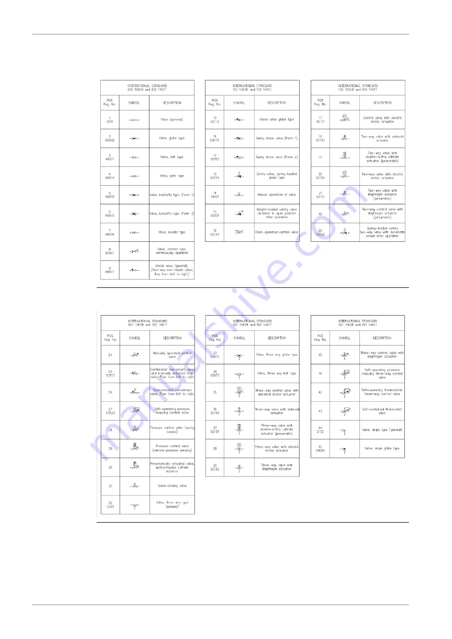
Страница 241: ...Fig 21 7 List of symbols DAAF406507 7 DBAD209883 21 5 21 ANNEX W rtsil 46DF Product Guide...

Страница 242: ...fficiency and data analytics W rtsil maximises the environmental and economic performance of the vessels and power plants of its customers W rtsil is listed on the NASDAQ OMX Helsinki Finland See also...

Отзывы: