


Page | 67
The surface temperature of the heater must not exceed 150°C in order to avoid cooking of the oil.
The heaters should be provided with safety valves and drain pipes to a leakage tank (so that
possible leakage can be detected).
Separator (2S01)
The separators should preferably be of a type with controlled discharge of the bowl to minimize the
lubricating oil losses.
The service throughput
Q
[
l/h
] of the separator can be estimated with the formula:
where
:
Q = volume flow [l/h]
P = engine output [kW] n = 4 for GAS
t = operating time [h/day]: 24 for continuous separator operation, 23 for normal dimensioning
Sludge tank (2T06)
The sludge tank should be located directly beneath the separators, or as close as possible below
the separators, unless it is integrated in the separator unit. The sludge pipe must be continuously
falling.
7.2.2
System oil tank (2T01)
Recommended oil tank volume is stated in chapter
Technical data.
The system oil tank is usually located beneath the engine foundation. The tank may not protrude
under the reduction gear or generator, and it must also be symmetrical in transverse direction under
the engine. The location must further be such that the lubricating oil is not cooled down below
normal operating temperature. Suction height is especially important with engine driven lubricating
oil pump. Losses in strainers etc. add to the geometric suction height. Maximum suction ability of
the pump is stated in chapter
Technical data.
The pipe connection between the engine oil sump and the system oil tank must be flexible to
prevent damages due to thermal expansion. The return pipes from the engine oil sump must end
beneath the minimum oil level in the tank. Further on the return pipes must not be located in the
same corner of the tank as the suction pipe of the pump.
The suction pipe of the pump should have a trumpet shaped or conical inlet to minimise the
pressure loss. For the same reason the suction pipe shall be as short and straight as possible and
have a sufficient diameter. A pressure gauge shall be installed close to the inlet of the lubricating
oil pump. The suction pipe shall further be equipped with a non-return valve of flap type without
spring. The non-return valve is particularly important with engine driven pump and it must be
installed in such a position that self-closing is ensured.
Suction and return pipes of the separator must not be located close to each other in the tank.
The ventilation pipe from the system oil tank may not be combined with crankcase ventilation pipes.
It must be possible to raise the oil temperature in the tank after a long stop. In cold conditions it can
be necessary to have heating coils in the oil tank in order to ensure pumpability. The separator
heater can normally be used to raise the oil temperature once the oil is pumpable. Further heat can
be transferred to the oil from the preheated engine, provided that the oil viscosity and thus the
power consumption of the pre-lubricating oil pump does not exceed the capacity of the electric
motor.
Содержание 31SG
Страница 1: ...Page 1 PRODUCT GUIDE W rtsil 31SG...
Страница 4: ...Page 4 This page intentionally left blank...
Страница 8: ...Page 8 This page intentionally left blank...
Страница 14: ...Page 14 This page intentionally left blank...
Страница 21: ...Page 21 This page intentionally left blank...
Страница 43: ...Page 43 This page intentionally left blank...
Страница 49: ...Page 49 Fig 5 1 Flexible hoses...
Страница 52: ...Page 52 This page intentionally left blank...
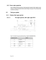
Страница 58: ...Page 58 Fig 6 4 Gas valve unit reference P I diagram DAAF051037D...
Страница 60: ...Page 60 Fig 6 7 Gas valve unit P I diagram open type DAAF085795A...
Страница 64: ...Page 64 Fig 7 2 Lubricating oil system single engine wet sump DAAF301501B...
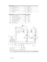
Страница 65: ...Page 65 Fig 7 3 Lubricating oil system Gas multiple engines wet sump DAAF301500A...
Страница 72: ...Page 72 This page intentionally left blank...
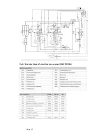
Страница 77: ...Page 77 Fig 9 1 Example diagram for multiple main engines DAAF301505A...
Страница 87: ...Page 87 This page intentionally left blank...
Страница 98: ...Page 98...
Страница 109: ...Page 109 This page intentionally left blank...
Страница 113: ...Page 113 This page intentionally left blank...
Страница 119: ...Page 119 This page intentionally left blank...
Страница 122: ...Page 122 18 4 1 Service space requirement 18 4 1 1 Service space requirement engine...
Страница 124: ...Page 124 This page intentionally left blank...
Страница 127: ...Page 127 This page intentionally left blank...
Страница 129: ...Page 129 This page intentionally left blank...
Страница 132: ...W rtsil 31SG Product Guide Page 132 21 2 Collection of drawing symbols used in drawings...


