background image

©2017 Warn Industries, Inc. WARN® and the WARN logo are trademarks of Warn Industries Inc.

 8 

105714A0

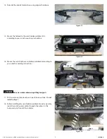
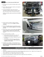
Figure 17

WARNING 

 Always use assistance when moving or lifting heavy parts.

19.  With assistance, line up the semi hidden weldment/winch 

assembly.

20.  Slide it underneath the bumper and then up into position 

(lining up mounting studs). 

21.  The winch control pack is the part that must pass 

underneath and into the space you trimmed out.  NOTE:  

More trimming may be necessary to obtain accurate fit. 


NOTE:  Be sure to keep winch power cables clear of weldment 

assembly.


22.  Once accurate fit is achieved, install the four factory 

mounting nuts (

4 per side

).  

Do not tighten to allow for 

adjustment.

23.  Adjust and center the bumper and semi hidden assembly 

horizontally.  

NOTE:  Horizontal adjustment is at the frame 

pad studs.

23.  Align the stock bumper vertically.  

NOTE:  Vertical alignment 

of the stock bumper is adjusted at the bumper bracket 

vertical slots.


TIP: We recommend using a floor jack to help 

with this. 

24.  Now that all the hardware is installed: 

a)  Check to make sure that there isn’t to much space 

between the frame brackets and the bumper. 

b)  Confirm bumper is centered and aligned vertically and 

horizontally. 

c)  Once satisfied with alignment, torque all hardware 

to suggested values on page 2. 

NOTE:  Always make 

adjustments with assistance.

25.  Installation is now complete.  Use the two bolts (5) and 

nuts (4) to install license plate to the front of the weldment. 

NOTE:  Plastic plugs (6) are included for the two lower front  

winch access holes.

Factory nuts

Figure 18

M A I N T E N A N C E   /   C A R E

1.  Inspect all parts on the winch, winch mount, and related hardware prior to each use.  Replace all hardware that appears rusted or 

deformed.

2.   Inspect all nuts and bolts on the winch, winch mount,, and related hardware prior to each use.  Tighten all nuts that appear to be 

loose.  Stripped, fractured, or bent bolts or nuts need to be replaced.

3.   Check all cables prior to use.  Replace cables that look worn or frayed.
4.   Check all moving or rotating parts.  Remove debris that may inhibit the part from moving freely.

Figure 19

Содержание 103209

Страница 1: ...electricalterminals Alwaysinstallterminalbootsasdirectedininstallationinstructions Alwaysuseappropriateandadequatecareinliftingcomponentsintoplace Alwaysinsurecomponentswillremainsecureduringinstallationandoperation Alwaystightenallnutsandboltssecurely pertheinstallationinstructions Alwaysperformregularinspectionsandmaintenanceontheplowmechanism fasteners cableandrelatedhardware Alwaysreplaceallwo...

Страница 2: ...cifications page 2 Parts List page 3 Installation page 4 8 Maintenance Care page 8 T O O L S R E Q U I R E D Standard wrenches Standard sockets Reciprocal saw or other cutting tool B E F O R E Y O U B E G I N N O T I C E This product may interfere with driver assist systems such as adaptive cruise control and parking assist systems that have sensors or cameras installed in the bumpers or front gri...

Страница 3: ... Inc 3 105714A0 P A R T S L I S T ITEM PART NO DESCRIPTION QTY 1 103206 LH BUMPER BRACKET 1 2 103195 RH BUMPER BRACKET 1 3 102846 SEMI HIDDEN WELDMNT 1 ITEM PART NO DESCRIPTION QTY 4 83125 M6 X 1 0 NUT 2 5 64108 M6 1 0 x 25 BOLT 2 6 102248 BLACK PLASTIC PLUG not shown 2 2 1 3 4 5 ...

Страница 4: ...m socket remove grille by removing the four front center screws as well as the two outer push pins 2 Remove one plastic clip from fender liner both sides 3 Using a 17mm socket remove the two bolts securing the tow hook each side Remove tow hook and set aside Save tow hook and bolts for reuse Figure 1 Figure 2 Figure 3 Plastic clips 10mm bolts Plastic clip ...

Страница 5: ...upcoming installation 5 From underneath the bumper use a 14mm socket to remove the four nuts each side holding the bumper structure to the frame rails Save nuts for reuse 6 If equipped disconnect harness from rear of fog lamps and disconnect park sensor harness both sides WARNING Always use assistance when moving or lifting heavy parts 6 Remove and set aside bumper Figure 5 Figure 6 Figure 4 ...

Страница 6: ...using the six reinforcement bar nuts 12 From the outside of the bumper use a reciprocating saw or similar tool to carefully cut out the center plastic following styling lines Tip Mask cut lines to prevent unnecessary damage NOTE Relocating the control pack can be done to avoid next step For winches with top mounted control pack only 13 From the inside of the bumper carefully cut a 10 x 2 inch sect...

Страница 7: ...ing instructions 16 Mount the winch to the semi hidden weldment according to your winch mounting instructions WARNING Always use assistance when moving or lifting heavy parts 17 With assistance place bumper in position on vehicle Do not install nuts yet 18 Before installing the semi hidden weldment winch assembly route the winch power cables through the cutout in the bumper and in front of the rad...

Страница 8: ...commend using a floor jack to help with this 24 Now that all the hardware is installed a Check to make sure that there isn t to much space between the frame brackets and the bumper b Confirm bumper is centered and aligned vertically and horizontally c Once satisfied with alignment torque all hardware to suggested values on page 2 NOTE Always make adjustments with assistance 25 Installation is now ...

Отзывы: