23 March 2017
Due to continued product improvement, Warmington Ind LTD reserves the right to change product specifications without prior notification.
All Dimension are in mm……….Copyright
15
FLUE DETAILS DIMENSIONS
Minimum Flue Height
Flue Height
3600
Measured From Top of Adaptor
B + F + 3600
Flue Details
No:
Evoque
Cowl
1
300
Top Spider
1
300
Cone
1
300
Flue Diameter
3
300
Liner Diameter
3
400
Spacer
3
300/400
NOTE:
Ensure that a standard tested Warmington flue system is used on the Warmington fires.
FLUE SYSTEM INSTALLATION GUIDE ONLY
1.
Install the first length of flue pipe with the crimped end down, inside the Adaptor collar, ensure that the flue
pipe is sealed into the collar with exhaust sealant. Rivet the flue in 3 places around the Adaptor collar.
Place a spacer around the flue pipe approximitaly150mm above the adaptor collar. Secure in position by
tightening the screw and nut.
2.
Install the second length of flue pipe with the crimped end down and fit by riveting in at least 3 places
around the flue pipe joint. Ensure that the flue is sealed into position with sealant.
3.
Install the first section of flue pipe liner with the Crimped end up, over the flue pipe and over the spacer that
is fixed to the flue pipe. This spacer will keep the liner concentric about the flue pipe.
4.
Position flue spacer at the flue pipe joint for every length of “Flue pipe” and “Liner”.
Repeat the Steps from 1
-
4 to the installed required height of the flue system. The flue system is to comply with
ASNZS 2918:2001 4.9.1
1.
NOTE:
The last length of flue pipe needs to extend past the liner so that when the “top spider” and the
“flashing cone” are fitted, that the “flashing cone” and the “flue pipe” are
flush,
or that the “flue pipe” is
5mm lower
than the “flashing cone”.
2.
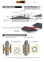
Fit the “top Spider” into position, ensure that the legs of the spider are fitted inside the liner and that the
spider is positioned hard down onto the liner and tighten with the screw and nut.
3.
Place the “flashing cone” over the “flue pipe” and press hard down onto the “top Spider”. Note that the
“flue pipe” and the “flashing cone” are either flush or the “flue pipe” is 5mm lower than the “flashing
cone”. Ensure that the “flashing cone” is clear for the venting from the “liner” and the “flue pipe”.
4.
Fit the “cowl” to the top of the flue pipe. The “cowl”, “flashing cone”, and the “flue pipe” can be secured to
each other with the uses of a stainless steel self tapping screw. This will allow the “cowl” to be removed
for cleaning.
5.
Flue system may require bird proofing due to the installation and locations, discuss this with your install-
er for the best advice.
6.
If the flue system is installed into a “chimney chase”, allow for air vent as close to the top of the chase as
practical, or allow venting through the “chimney chase flashing”. A “venting flashing cone” and a 25mm
gap around the liner with a “venting flashing cone
-
spider” can be used. Refer to figures.
•
a “the flue pipe shall extend not less than 4.6m above the top of the floor protector.”
•
b “ the minimum height
of the flue system within 3 m distance from the highest point of the roof shall be 600mm
above that point.”
•
c “the minimum height of the flue system further than 3 m from the highest point of the roof shall be 1000mm
above the roof penetration.”
•
d “no part
of any building lies in or above a circular area described by a horizontal radius of 3 m about the flue
system exit.”
Single 3.6m Flue Kit Details
NOTE: FLUE SYSTEMS CASING
Flue system may require to be doubled lined to comply.
Refer ASNZS:2918:2001 4.3 flue pipe casing.
This is a general installation guide only – Contact a “NZHHA Installer” for installation
advice or go to www.homeheat.co.nz then select Members & follow instructions, to
find a certified NZHHA SFAIT installer.


