


Replacing Switch and Power Close Hoses
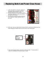
6. Secure the hoses to the front cover leaving 8” and 16” of hose exposed from the
edge of the lower guard.
7. Secure the switch wire to the outside guard using the holes provided using wire ties.
8. Secure the other end of the hose with shield to the inside guard using bolts and
brackets removed in step 4.
9. Install outside guard back in place using the two bolts.
10. Refasten the switch to the column using the two bolts.
8” from edge of guard
for hose 75489469
female end.
16” from edge of
guard for hose
75489466 – female
end
16”
8”
43
Содержание WDV
Страница 15: ...Electric Hydraulic Flow Schematics Power Up S4 Valve Coil activated for Up function 15...
Страница 16: ...Electric Hydraulic Flow Schematics Power Down S3 S4 Valve Coil activated for the Down function 16...
Страница 17: ...Electric Hydraulic Flow Schematics Power Close S1 Valve Coil activated for the Close function 17...
Страница 18: ...Electric Hydraulic Flow Schematics Power Open S1 S2 Valve Coil activated for the Open function 18...
Страница 19: ...Electric Hydraulic Schematics Built from 4 09 thru 10 11 Single pump Motor Single Relay 19...
Страница 20: ...Electric Hydraulic Schematics Built from 4 09 thru 10 11 Dual Pump Motor with Back Up Auxiliary Single Relay 20...
Страница 21: ...Electric Hydraulic Schematics Built from 10 11 Single Pump Motor Dual Relay 21...
Страница 22: ...Electric Hydraulic Schematics Built from 10 11 Dual Pump Motor with Backup Auxiliary Dual Relay 22...
Страница 23: ...Work Light Electrical Hydraulic Schematic 23...
Страница 28: ...28...
Страница 29: ...29...
Страница 30: ...30...
Страница 31: ...31...
Страница 48: ...Notes 48...


