manualshive.com logo in svg
background image

XC Duo

Asennus-, käyttö- ja huolto-ohjeet

fi 

en

de

Montage-, Bedienungs- und Wartungsanleitung

Installation, operation and service instructions

Содержание xs duo

Страница 1: ...XC Duo Asennus k ytt ja huolto ohjeet fi en de Montage Bedienungs und Wartungsanleitung Installation operation and service instructions...

Страница 2: ...nection 51 Fuel connections 51 Things to note about the connections 51 Country specific requirements 51 Fuel feed 51 Connection to a fixed tank 51 Connection to a separate tank 51 Wallas fuel tanks 52...

Страница 3: ...of the cooking plate 67 Cleaning and maintaining the stove top 68 Maintenance 68 Fault signals and releasing the lock 69 Maintenance recommendations 69 Cleaning the exhaust head 69 Basic maintenance...

Страница 4: ...ssories Exhaust tube 28 mm inox Heat insulation 30 mm Fiber glass Bracket set Cover plate kit XC Duo Installation kit Tank fitting Cu Tank feed through diesel 4 m Standard delivery Installation access...

Страница 5: ...70 Plastic cover for exhaust head 368202 1 pcs 1 pcs Exhaust head Fastening screw M5 x 10 Exhaust head 4300 Locking nut M5 Washer M5 1 pcs 1 pcs 4 pcs 2 pcs 2 pcs 1 pcs 4 pcs 1 pcs Extension collar 1...

Страница 6: ...is transferred into the ceramic stove top The left side of the stove top is hotter as the burner is located under it The power of the stove can be adjusted steplessly The control adjusts both sides o...

Страница 7: ...yield optimal performance while inclined The control panel should be installed in a vertical surface away from sources of heat or cold for thermostatic function and within the 3 meter control harness...

Страница 8: ...s heat to its sur roundings and the control panel thermostat and Sun Switch will not operate as planned if installed too close to the unit Select the location for the control panel to suit the intende...

Страница 9: ...ber the locking nuts M6 5 Attach the steel fasteners to the stove 1 with screws 2 The steel fasteners can be installed in two ways depending on the thickness of the table board Push the cover plug 3 o...

Страница 10: ...oose cables and fuel line by creating a coil If the installation location is cramped it is recommend to connect the cabels and the fuel line to the device before mounting the unit to bracket This will...

Страница 11: ...rews You can utilize the sample of the box when drawing the lines of the installation hole Connect the control panel cable from the device to the control panel 1 Use the fastening screws to install th...

Страница 12: ...um length of the power cord is 10 m based on 6 AWG cable Total length of the power cord m Cross sectional area of the cable in square mm US Gauge If a thicker cable is required make a separate joint i...

Страница 13: ...uires After the 12 V battery the connec tion is the same as in a 12 V system 24 V direct current system Device s quick coupling Jointing A jointing should only be made in long power cords if necessary...

Страница 14: ...feed If the lift height exceeds 2 m the fuel feed must be checked and if necessary ad justed The fuel feed must also always be checked if parts of the fuel system such as the pump or the electronics...

Страница 15: ...selected area of protection grease and clean also other pos sible dirt Drill a hole Remove the burr from hole inside and outside Figure out without installing for Einon 30018 suitable bending and leng...

Страница 16: ...e fuel will be taken from a separate tank you must install a tank connection 367215 4 m 367216 6 m Disconnect the fuel line which is leading from the fuel filter to device Replace it with fuel line of...

Страница 17: ...between the pump and the filter as they will clog the pump The filter type must be selected ac cording to the operating conditions and country specific requirements Fuel filter 30014 accessory This fi...

Страница 18: ...re drops lower than the minimum level paraffin may form in the fuel This may result in the fuel filter and pump being clogged The clog will dissolve only if the fuel temperature rises clearly over 0 C...

Страница 19: ...n the middle of the vehicle the exhaust head will reduce ground clearance the most The minimum distance of the exhaust head from the fuel tank s filler hole is 400 mm 16 The front edge of the exhaust...

Страница 20: ...es Installation When you have chosen the location for the 4300 exhaust head you should find the best place to lead the combustion gas and intake air hoses through the bottom of the vehicle Drill two h...

Страница 21: ...ack Note the connection points of the hoses on the exhaust head the intake air hose is installed on the reduced hose fitting on the 4300 exhaust head while the combustion gas hose is fitted on 28 mm h...

Страница 22: ...ear tyres The combustion gas is ex hausted through the smaller opening in the plastic frame of the exhaust head and seen from the rear of the head the combustion gas exhaust hose is fixed on the unred...

Страница 23: ...to the vehicle bottom There are many possible ways to install the 4300 exhaust head to the vehicle s bottom structure The 4310 basic chassis installation kit can be used to install the combustion gas...

Страница 24: ...oses and the chassis install the plastic frame on the exhaust head The frame is in stalled with the smaller opening on the combustion gas exhaust side Make sure that the claws of the plastic strips lo...

Страница 25: ...on a vertical surface where liquids are not able to leak into the panel and it is out of reach of chil dren cable length 3 m F F The control panel is installed in a location where its thermostat can b...

Страница 26: ...A red combustion indicator light 1 will be lit when the burner flame has been ig nited and the combustion has stabilised after about five minutes after the ignition The whole process takes about 11 m...

Страница 27: ...there is enough ventilation Normal Use The power is adjusted manually The cooker will always ignite in manual mode After the ignition power can be adjusted step less with the power control 2 knob Avo...

Страница 28: ...ce signals that manual function has been activated when the thermostat light 5 shuts off After the heater has been started up the power can be adjusted smoothly with the power adjustment knob 2 From m...

Страница 29: ...n the device is used more than 1300 meters 4200 feet above sea level This function increases the amount of combus tion air in thin air The high altitude mode is turned on by pressing the heating switc...

Страница 30: ...dirt and food scraps with a cleaning spatula Put a few drops of a cleaning agent for ceramic surfaces on the stove top and wipe it with a piece of paper towel Then wipe the stove top with a moist clo...

Страница 31: ...out 5 minutes after fault indication Blink interval Fault description If the heater has locked itself you must determine the cause for the locking before releasing it RELEASING THE LOCK 1 When the lig...

Страница 32: ...ability by purging old fuel If the device uses the same tank as the engine Observe the engine manufacturer s recommendation with regard to the fuel type and moisture removal If the device has a separa...

Страница 33: ...Drain the fuel tank in the autumn Clean the tank and change the fuel filter Fill the fuel tank with fresh and clean fuel in the spring For the device itself you do not need to do anything Spare parts...

Страница 34: ...is blocked The piston makes weak ticking sound vibration when it s moving normally Knock the body of the pump to get the piston to move again The filter is blocked Change the filter to a new one Bad...

Страница 35: ...e in the power supply Check and clean the contacts of the connectors Start the engine The charging voltage increases the voltage of the battery Check the condition of the battery and the power cables...

Страница 36: ...ting flameout The fuel has run out or its level is too low for the intake hose in the tank to reach it High wind pressure at the exhaust lead through fitting Water in the exhaust gas hose Water in the...

Страница 37: ...repairs are carried out while the unit is fitted to the vehicle d The customer must provide the following information in writing for warranty service description of the problem a description of where...

Страница 38: ...s spare part no FUEL PUMP FC 1 CONTROL UNIT XP360 THERMO ELEMENT GASKET FOR T4 THERMO ELEMENT OVERHEAT THERMOSTAT spare part no COMBUSTION BLOWER XC Duo HINGE ROLLER SET GLOW PLUG RADIATION ELEMENT BO...

Страница 39: ...A 1 2 3 5 6 7 8 9 10 11 12 13 14 15 en Spare parts D50371B 110 XC Duo 490541G...

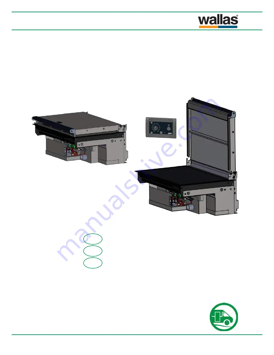
Страница 40: ...18 4 17 en Spare parts D50371B 111 XC Duo 490541G...

Страница 41: ...D90019 112 490541G...

Страница 42: ...490541G...

Страница 43: ...Oikeudet muutoksiin pid tet n We reserve the right to changes nderungen vorbehalten Wallas Marin Oy K rrykatu 4 20780 Kaarina Finland www wallas com 490541G...

Отзывы: