background image

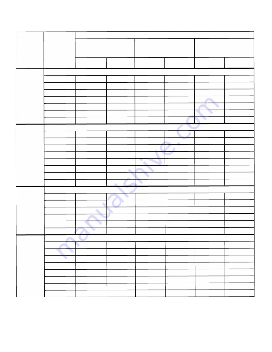
LIFTING GUIDELINES BM

PLATE 

TYPE OF SURFACE 

CLEAN &  SMOOTH 

RUST OR SCALE 

IRREGULAR OR ROUGH 

MAGNET 

WORKPIECE  Simila r to a  flat ground  surface  Simila r to a  flat hot rolled  steel 

Simila r to a  flat smooth cut 

MODELS 

THICK NESS 

32  microinch RMS.000" 

surface.01 O" (.254 mm) 

file.020" (.508 mm) 

Max.  Air Gap 

Max.  Air Gap 

Max.  Air Gap 

Max.  Load 

Max.  Size 

Max.  Load 

Max.  Size 

Max.  Load 

Max.  Size 

(lbs.) 

(ft.) 

(lbs.) 

(ft.) 

(lbs.) 

(ft.) 

NEVER LIFT ANY  LOADS WITH ANY  DIMENSION GREATER THAN 9  FEET 

OVER 1-1/2" 

3000 

-

2575 

-

2000 

-

1-1/2"

3000 

7x7 

2575 

6x7 

2000 

5x6 

*1"

2100 

7x7 

1975 

6x7 

1700 

5x6 

BM

2

-13PB 

*3/4" 

1475 

7x6 

1300 

6x6 

1100 

5x6 

*1/2"

825 

6x6 

750 

6x6 

650 

5x5 

*3/8"

475 

5x6 

425 

5x5 

400 

5x5 

*1/4"

200 

4x4 

190 

4x4 

175 

4x4 

NEVER LIFT ANY  LOADS WITH ANY  DIMENSION GREATER THAN 15  FEET 

OVER2" 

5500 

-

4650 

-

3850 

-

*2" 

5500 

8x8 

4650 

7x8 

3850 

6x7 

*1-1/2"

4075 

8x8 

3575 

7x8 

2975 

6x7 

BM

2

-25PB 

*1"

2650 

8x8 

2500 

7x8 

2100 

7x7 

*3/4" 

1650 

7x7 

1450 

6x7 

1350 

6x7 

*1/2"

825 

6x6 

800 

6x6 

725 

5x7 

*3/8" 

475 

5x6 

450 

4x7 

400 

5x5 

*1/4"

210 

4x5 

190 

4x4 

180 

4x4 

NEVER LIFT ANY  LOADS WITH ANY  DIMENSION GREATER THAN 20  FEET 

OVER2" 

8000 

-

7200 

-

6000 

-

*1"

8000 

9x20 

7200 

8x20 

6000 

18 

BM

2

-36PB 

*3/4" 

5350 

8x20 

4900 

8x20 

4320 

17 

*1/2"

2000 

12 

1925 

11 

1850 

11 

*3/8" 

1100 

8x9 

1025 

8x8 

950 

7x8 

*1/4"

550 

6x9 

525 

6x8 

500 

6x8 

NEVER LIFT ANY  LOADS WITH ANY  DIMENSION GREATER THAN 25  FEET 

OVER2" 

11000 

-

9300 

-

7700 

-

*2" 

11000 

11 

12 

9300 

10 

11 

7700 

10 

*1-1/2"

8150 

11 

11 

7150 

10 

11 

5950 

9x 10 

BM

2

-50PB 

*1"

5300 

11 

11 

5000 

11 

11 

4200 

10 

10 

*3/4" 

3300 

10 

2900 

9x 10 

2700 

9x9 

*1/2"

1650 

8x9 

1600 

8x9 

1450 

8x8 

*3/8" 

950 

7x8 

900 

7x8 

800 

7x7 

*1/4"

420 

6x6 

380 

6x6 

360 

5x6 

• 

LIFTING CAPACITY AFFECTED BY PEEL AND THICKNESS. SEE 1 

4 OF THE "IMPORTANT FACTS" (PAGE 8 

9) IN THIS INSTRUCTION MANUAL. 

t SEE SECTION 6 OF THE "IMPORTANT FACTS" (PAGE  9) IN THIS INSTRUCT/ON MANUAL.  ALSO, READ RECOMMENDED LIFTING PROCEDURES (PAGE 12). 

Values shown are maximum rated capacities when all operating instructions and warnings are strictly followed. Values based on SAE 1020. 

Higher alloy steels and other magnetic materials will require further reductions of these rated capacities. 

(See Guidelines for the Reduction of Rated Lifting Capacity.) 

O. S.  Wa lker Inc.,  Battery Powered  Magn ets 

15 

Содержание BUX BM2

Страница 1: ...GNETS MODELS BUX BM2 BUX BP2 BUX BM2 13PB BUX BM2 25PB BUX BM2 36PB BUX BM2 50PB BUX BP2 7PB BUX BP2 15PB ADANGER Always stay clear Never lift loads over Never attempt to operate either of of the load people or in close these magnets until you have read and proximity to people understand this Operator s Manual ...

Страница 2: ...r Product If used and maintained properly it will serve you for many years Thousands of O S Walker lift magnets are in service today doing safe fast and efficient magnetic material handling It is often the most efficient way for one person to load transport and un load material O S Walker Products have proven to be among the best designed and safest in our industry however if used improperly any M...

Страница 3: ...ans port people Never leave any lifted load unattended Never lift more than one work piece at a time with this magnet Always make sure that the supporting struc ture and load attaching devices i e crane chains and hook are rated to support the weight of the magnet and load Always make sure that the load s weight and dimensions are within the Magnet s Lifting Guidelines These Guidelines are located...

Страница 4: ...rious injury or death This indicates a potentially hazardous situ ation which could result in minor injury or moderate injury These are Hazard Seriousness Signal Words UNSAFE LIFTING APPLICATIONS FOR YOUR MAGNET Never lift any pipe solid round or struc tural shapes with this magnet Never lift any castings that do not have a machined flat lifting surface for the magnet The location of the lifting s...

Страница 5: ...ing and Warning labels Persons using pacemakers or other medical de vices should not use this magnet until they have consulted with their physician A WARNING Disassembly or repair of this magnet can result in reduced holding power and or cause an unsafe condition Therefore anytime the magnet is disassembled beyond the parts list shown in this manual the magnet must be re tested for break away forc...

Страница 6: ... red battery cable to the positive post marked and cover with the terminal boot THEN connect the black battery cable to the negative post marked BATTERY CHARGING Read and understand the instructions supplied with your battery After installation the battery should be charged as soon as possible to avoid loss of life Make sure the battery has been fully charged before placing the magnet into service...

Страница 7: ...5 27 72 29 97 Net Weight lbs 191 260 565 645 350 739 Performance Rating on AISI 1020 Steel Performance Rating on AISI 1020 Steel BUX BM2 13PB 0 3 000 lbs Rated Lift BUX BM2 25PB 0 5 500 lbs Rated Lift BUX BM2 36PB 0 8 000 lbs Rated Lift BUX BM2 50PB 0 11 000 lbs Rated Lift BUX BP2 7PB 0 1 665 lbs Rated Lift BUX BP2 15PB 0 3 330 lbs Rated Lift All model BM2 BP2 Lifting Magnets are rated for 50 Duty...

Страница 8: ...ugh air however they do flow very easily through iron As a result anything that creates a space or an air gap between a magnet and the load will limit the flow of magnetic lines of force thus reducing the lifting capacity of the magnet Magnet s Lifting Surface Condition The lifting surfaces of a magnet must be clean smooth flat and free of nicks and burrs in order to minimize the air gap between a...

Страница 9: ...As the slope of the magnet s lifting surface changes from horizontal to vertical the lifting capacity of the magnet decreases When the magnet s lifting surfaces are vertical the lifting capacity of the magnet is minimum and dependent upon the coefficient of friction between the magnet s lifting surface and the load 6 PORTION OF MAGNET SURFACE IN CONTACT WITH LOAD The full surface of the magnet mus...

Страница 10: ...AY CLEAR OF THE LOAD 2 Check the condition of the magnet prior to every lift WIPE clean the bottom of the magnet and the area on the load where the magnet will be located File away burrs 6 Lift and move the load SMOOTHLY Avoid jarring and swinging the load while it is in transit KEEP THE LOAD LEVEL NEVER let the load come in contact with any obstruction If you have any difficulty lifting a load DO...

Страница 11: ...hile the magnetic energy builds up When the magnetic energy builds up to a sufficient level the alarm will stop sounding The indicator lamps will now show the battery charge level This might take a few seconds IF THE ALARM CONTINUES SOUNDING OR THE RED DANGER LAMP STAYS ON DO NOT OPER ATE THE MAGNET TURN THE MAGNET OFF 8 Carefully set the load down To release the load press the RELEASE button on t...

Страница 12: ... with the load When the load width is narrower than the width of the magnet position the magnet so the length of the magnet is parallel to the width of the load This allows for maximum and equal amounts of each pole area in contact with the load UNSAFE LIFTING APPLICATIONS FOR YOUR MAGNET Never lift any pipe solid round or struc tural shapes with this magnet A DANGER 1 11 1 Never lift any castings...

Страница 13: ... MATERIAL OTHER THAN SAE 1020 STEEL Reduction Factors for Materials Other than SAE 1020 Steel Materials Cast Steel 3 Silicon Steel SAE 1095 Steel 16 Stainless Steel Cast Iron non chilled Pure Nickel REDUCTION FACTOR 0 90 0 80 0 70 0 50 0 45 0 10 For Other Materials Consult O S Walker Rated Lifting Capacity for these materials Reduction Factor multiplied by Maximum Load Value for 1020 Steel from Li...

Страница 14: ... Length of Square Bar Feet DUTY CYCLE DO NOT EXCEED THE RATED 50 DUTY CYCLE OF THESE MAGNETS Exceeding the duty cycle will result in reduced lifting capacity less operating time between battery charges and a reduc tion in the life of the magnet Duty cycle rating D C is defined as Time On x 100 Time Off Time On D C and is expressed as a Percent with a maximum of 10 minutes Time On Therefore to maxi...

Страница 15: ...VER LIFT ANY LOADSWITH ANY DIMENSION GREATER THAN20 FEET OVER2 8000 7200 6000 1 8000 9x20 7200 8x20 6000 8 X 18 BM2 36PB 3 4 5350 8x20 4900 8x20 4320 8 X 17 1 2 2000 8 X 12 1925 8 X 11 1850 8 X 11 3 8 1100 8x9 1025 8x8 950 7x8 1 4 550 6x9 525 6x8 500 6x8 NEVER LIFT ANY LOADSWITH ANY DIMENSION GREATER THAN25 FEET OVER2 11000 9300 7700 2 11000 11 X 12 9300 10 X 11 7700 9 X 10 1 1 2 8150 11 X 11 7150...

Страница 16: ... 7x7 715 6x7 1 4 630 7x8 550 7x7 530 7x7 LIFTING GUIDELINES STRUCTURAL SHAPES MAGNET MODELS MATERIAL TYPE MATERIAL SIZE BP2 7PB BP2 15PB M s fT MAX 1tl NGTH M s fT MAX 1tl NGTH 1 4 3 8 WEB 330 20 530 20 BEAMS CHANNELS 7 16 1 2 WEB 500 20 815 20 REDUCE CAPACITY BY 5 8 3 4 WEB 830 20 1450 20 WHEN LIFTING ON FLANGE 7 8 1 WEB 1000 20 1865 20 ABOVE 1 WEB 1665 20 3330 20 1 THRU 5 1 2 DIA 20 20 SOLID BAR...

Страница 17: ...een indicator turns off shortly after the magnet has been turned on this could indicate the battery s inability to retain the charge level See Troubleshooting page 21 section C for more informa tion ADANGER Observe the battery charge level indicators frequently during each lift If the red DANGER indicator goes on and or the alarm sounds during a lift set the load down immediately INDICATOR DISPLAY...

Страница 18: ...lights on the bezel of the battery magnet and hold down the green LIFT button and the top red RELEASE button simultaneously Keep the buttons depressed until the row of lights on the battery magnet flash sequentially and the alarm sounds Then release the buttons and the magnet should be programmed to operate with the new remote and be ready for use If the process does not procede as described refer...

Страница 19: ...ct Always remove black battery lead first and connect it last Check the physical condition of all cables leads lamps and alarms Repair or replace any suspicious components Check the condition of the Operating Instruction label and Product Safety signs If these labels and signs are missing or damaged they should be replaced WEEKLY The lifting surfaces of the magnet should be checked for flatness an...

Страница 20: ...ce Resistance To Ground Coil Epoxy Encapsulation Lift Bail Bail Pin Click Pin Structural Weld Condition Labels Safety Instructions Date and Initial for each inspection Condition Date Initials Date Initials Magnet Face Electrical Wiring Indicator Lights Control Operation Coil Resistance Resistance To Ground Coil Epoxy Encapsulation Lift Bail Bail Pin Click Pin Structural Weld Condition Labels Safet...

Страница 21: ...Check the label located on the back of the control unit inside the battery compartment to be certain it is the correct control for your magnet model Controls are configured for use on specific models 1 After a complete battery charge ALL the charge level lamps should light when the LIFT button on the Front Panel or I R remote is pressed The green lamps will turn off as the battery dis charges and ...

Страница 22: ...they do not retain their full charge capacity Indications of the battery conditions may be observed by the charger requiring longer H BATTERY NOT periods of time to turn on the complete lamp green battery indicator or possibly not being able to CHARGING reach a charge level to turn on the complete indicator 14 If the magnet was left on and the battery allowed to drop below 8 volts the magnet s pow...

Страница 23: ...ment parts may be installed by a Designated Person AWARNING Disassembly or repair of this magnet can result in reduced holding power and or cause an unsafe condition Anytime the magnet is disassembled beyond the parts list shown in this manual the magnet must be re tested for breakaway force in accordance with the test described in ANSI ASME 830 20 Modification of any operating mechanism or struct...

Страница 24: ...16 44 BB14416 44 BB14416 44 BB14416 56 BXM4917A 56 BXM4917A 56 BXM4917A 56 BXM4917A 54 OD17036 54 OD17037 54 OD17038 54 OD17039 39 DO14069 39 DO14069 39 DO14069 39 DO14069 54 OD3591S 44 CC3279S 10 5484 10 5484 10 5484 10 5484 16 1037 16 1037 16 1037 16 1037 39 3744 39 3744 39 3744 39 3744 54 OD14974 54 OD14974 54 OD14974 54 OD14974 39 AA14294 39 AA14294 39 AA14294 39 AA14294 0 II r IOOJI 0 BP 7P B...

Страница 25: ...oad at all times DO NOT guide the load by pushing or pulling the magnet NEVER get in a position where you could get hit with the load if it is dropped 37 DD 16630M Rev April 3 2012 25 Walker Magnetics 600 Day Hill Road Windsor CT 06095 Walker National 2195 Wright Brothers Ave Columbus OH 43212 www walkermagnet com 800 WMAGNET ...

Отзывы: