OPERATOR’S MANUAL
20. Install the set screw into the lock nut, reference
Figure 7-6
, and tighten to the required
torque as specified in
Section 8: Specifications
.
21. Rotate the rotor assembly by hand to ensure it rotates smoothly and there are no
abnormal sounds from the bearing assembly such as crunching or grinding.
22. Install the seal plate, reference
Figure 7-5
, and tighten the seal plate fasteners to the
required torque as specified in
Section 8: Specifications
.
23. Repeat
Step 3
to
Step 22
for the other end plate and bearing.
24. Refer to the section
Rotor and Blade Tip Clearances
to ensure the rotor is properly
positioned with the correct clearances.
25. Ensure all guards have been installed and secured before operation of the airlock.
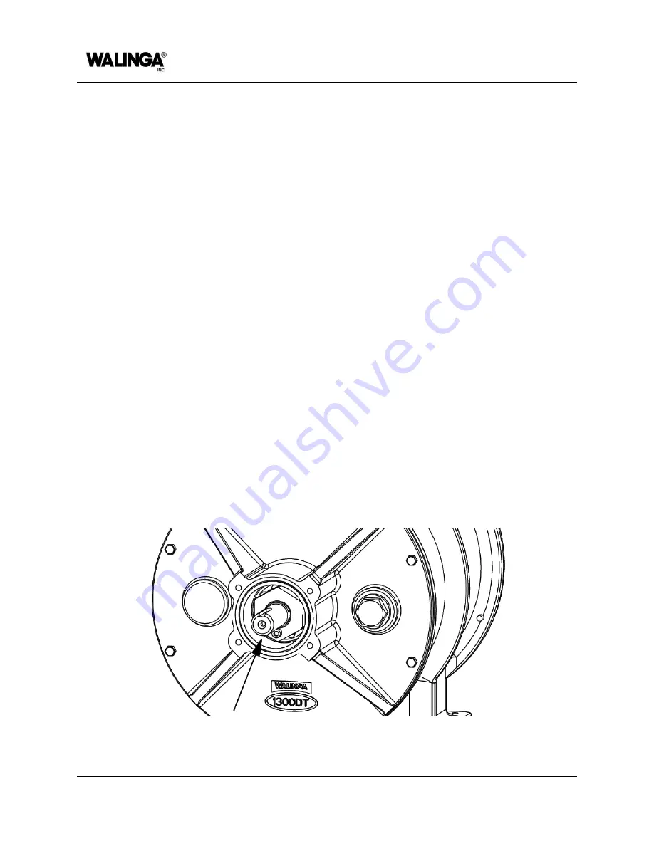
Bearing and Seal Cavity Inspection
To reduce damage and wear to the bearing, it is important that the bearing cavity is kept clean
and free of dirt, dust and debris. When conveying products with abrasive properties or high
levels of dust, it is possible for some contaminants to enter the bearing cavity, even when
abrasive style airlocks are equipped with a purge line.
To check the condition of the bearing cavity, proceed as follows:
1. Clear the area of bystanders, especially small children.
2. Place all controls in neutral, stop and lock-out the power source, and wait for all moving
parts to stop.
3. Remove the fasteners securing the seal plate in place and remove the seal plate,
reference
Figure 7-5
.
4. Inspect the inner surfaces of the cavity for dirt, dust or debris.
Figure 7-13: Bearing cavity
7-12
00-144477-0 A
MAINTENANCE AND ADJUSTMENTS
Содержание Airlock 1008
Страница 1: ...OPERATOR S MANUAL Airlock 1008 English 00 144471 0 A 2023 12 06...
Страница 7: ...Identification of Machine AIRLOCK MODELS 1 1...
Страница 9: ...Introduction AIRLOCK MODELS 2 1...
Страница 15: ...Machine Configuration AIRLOCK MODELS 3 1...
Страница 26: ...OPERATOR S MANUAL PAGE INTENTIONALLY LEFT BLANK 3 12 00 144473 0 A MACHINE CONFIGURATION...
Страница 27: ...Safety AIRLOCK MODELS 4 1...
Страница 38: ...OPERATOR S MANUAL DATE EMPLOYEE S NAME EMPLOYEE S SIGNATURE EMPLOYER S SIGNATURE 4 12 00 144474 0 A SAFETY...
Страница 39: ...Machine Life Cycle Procedures AIRLOCK MODELS 5 1...
Страница 45: ...Operation AIRLOCK MODELS 6 1...
Страница 54: ...OPERATOR S MANUAL PAGE INTENTIONALLY LEFT BLANK 6 10 00 144476 0 A OPERATION...
Страница 55: ...Maintenance and Adjustments AIRLOCK MODELS 7 1...
Страница 99: ...Specifications AIRLOCK MODELS 8 1...
Страница 108: ...OPERATOR S MANUAL PAGE INTENTIONALLY LEFT BLANK 8 10 00 144478 0 A SPECIFICATIONS...
Страница 109: ...Warranty AFTERMARKET PARTS AND SERVICE 9 1...
Страница 113: ...Accessories and Attachments AIRLOCK MODELS 10 1...
Страница 116: ...OPERATOR S MANUAL PAGE INTENTIONALLY LEFT BLANK 10 4 00 144480 0 A ACCESSORIES AND ATTACHMENTS...
Страница 117: ...Parts List AIRLOCK 1008 MODEL 11 1...
Страница 125: ...PAGE INTENTIONALLY LEFT BLANK...


