background image

Assembly 


All Models 

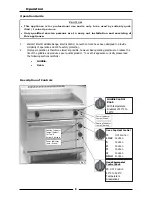
All models come pre-assembled. 


NOTE:  This appliance is fitted with adjustable feet / castors to enable the unit to be positioned  

securely and level.  This should be carried out on completion of the electrical connection.  
Refer to the 'Electrical Connection' section. 


Optional Accessories (Refer to Replacement Parts List) 



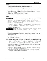
Plinth Kit.  For installation details, refer to the instructions supplied with each kit. 


Electrical Connection 

NOTE: ALL ELECTRICAL CONNECTIONS MUST ONLY BE CARRIED OUT BY AN AUTHORISED 

PERSON. 


Each appliance should be connected to an adequately protected power supply and isolation switch mounted 

adjacent to, but not behind the appliance.  This switch must be clearly marked and readily accessible in 
case of fire. 


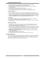
1. 

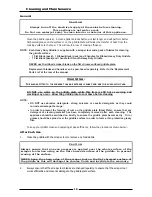
Check that the electricity supply is correct as shown on the Rating 

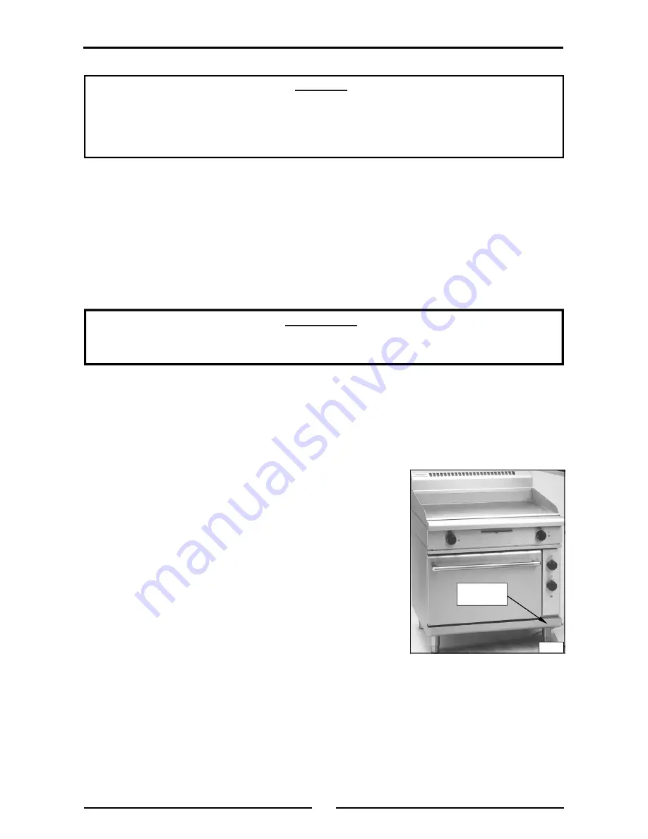
Plate.  (Refer to the dimension drawings for rating plate location). 

2. 

The supply terminal connections are located at the rear of the the 
appliance.  Refer to ‘Electrical Connections’ in the ‘Specifications’ 

section of the manual. 

3. 

Remove the control panel to allow connection access for the  

electrical supply. 

4. 

Bring the supply cable up through the grommet at the back of the 

appliance and through the compression type gland provided on 
the rear of the main electrical switchgear panel. 

5. 

Connect the mains supply to L1, L2 and L3 fuse carrier  

connections for 3 phase. 

6. 

Connect neutral and earth conductors to neutral stud and earth 

stud respectively. 

7. 

For all connections ensure that conductors are secure and  
appropriately terminated. 

8. 

Tighten the cable gland to secure against tension on the cable. 


NOTE: 



This appliance must be grounded / earthed. 



Fixed wiring installations must incorporate an all-pole disconnection switch. 


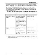
9. 

Correctly locate the appliance into its final operating position and using a spirit level, adjust the legs 

so that the appliance is level and at the correct height. 

10.  Connect the power supply to the appliance. 
11.  Check that the electrical supply is as shown in the 'Specifications' section. 

Installation


C

AUTION




This appliance is for professional use and is to be used by suitably  
qualified / trained persons only. 



Only qualified service persons are to carry out installation and servicing of 
this appliance.


WARNING: 


T

HIS


APPLIANCE


MUST


BE


EARTHED

.  I

F


THE


SUPPLY


CORD


IS


DAMAGED

IT


MUST


BE


REPLACED


BY


A


SUITABLY


QUALIFIED


PERSON


IN


ORDER


TO


AVOID


A


HAZARD

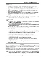
Fig 1 

Rating Plate 

Location 

Содержание GP8910E

Страница 1: ...o n a n d O p e r a t i o n M a n u a l GP8910E GP8910EC Electric Griddle Ranges Date Purchased Serial Number Dealer Service Provider 230379 8 For use in GB IE GPL8910E GPL8910EC GPB8910E GPB8910EC G...

Страница 2: ...ares tel 1800 337 963 Customer Service tel 1800 335 315 fax 1800 350 281 CANADA Serve Canada Web www servecanada com E Mail info servecanada com Sales tel 800 551 8795 Toll Free Service tel 800 263 14...

Страница 3: ...General Electrical Supply Requirements Electrical Connection Dimensions Installation 5 Installation Requirements Unpacking Location Clearances Assembly Electrical Connection Commissioning Operation 8...

Страница 4: ...PROPER INSTALLATION ADJUSTMENT ALTERATION SERVICE OR MAINTENANCE CAN CAUSE PROPERTY DAMAGE INJURY OR DEATH READ THE INSTALLATION OPERATING AND MAINTENANCE INSTRUCTIONS THOROUGHLY BEFORE INSTALLING OR...

Страница 5: ...ppliance to the main supply ensure that the following is carried out An isolating switch is fitted within 2 m of the appliance but not on the appliance and in such a position that the user does not ha...

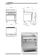
Страница 6: ...4 Dimensions GP L 8910E EC...

Страница 7: ...ed service agent They are not to be adjusted by the installation person Unpacking Remove all packaging and transit protection from the appliance including all protective plastic coating from the exter...

Страница 8: ...al supply 4 Bring the supply cable up through the grommet at the back of the appliance and through the compression type gland provided on the rear of the main electrical switchgear panel 5 Connect the...

Страница 9: ...ontacts have been added to the front of this manual b Ensure that the operator has been instructed in the areas of correct operation and shutdown procedure for the appliance 2 This manual must be kept...

Страница 10: ...scription of Controls Griddle Control Knob With temperature Gradient of 50 C to 320 C Heating Indicator Lamps Amber Power Indicator Lamps Green CAUTION This appliance is for professional use and is on...

Страница 11: ...maximum of 2 When the desired temperature is reached the amber neon will go out Cooking When the desired temperature has been reached load the oven with product and set the oven top heat control to t...

Страница 12: ...n the griddle plate Steel Plate ensure that any detergent or cleaning material has been completely removed after each cleaning The appliance should be switched on briefly to ensure the griddle plate b...

Страница 13: ...ddle Steel Plate NOTE In order to prevent the forming of rust on the griddle plate ensure that all detergent and cleaning material has been entirely removed after each cleaning process The appliance s...

Страница 14: ...ty domestic oven cleaner c Once a week remove and clean any built up of grease etc from the oven racks and the bottom spill over cover Stainless Steel Surfaces a Clean the exterior surfaces of the gri...

Страница 15: ...lem Please note that the service agent will require the following information The Model Trade Name and the Serial Number of the Appliance both can be found on the Technical Data Plate located on the a...

Страница 16: ...3 2 2 7 7 6 9 9 9 7 6 8 8 4 4 5 11 13 14 10 10 10 12 11 22 32 12 3 P3 4 P4 CONTROL PANEL GRIDDLE PLATE 21 31 11 22 32 12 15 16 15 16 THERMOSTAT 229146 SWITCH 229145 2 1 P2 P1 NEON GREEN 227962 NEON AM...

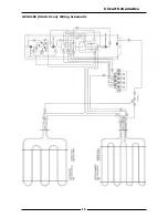
Страница 17: ...15 Circuit Schematics GP8910E Static Oven Wiring Schematic...

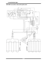
Страница 18: ...16 Circuit Schematics GP8910EC Convection Oven Wiring Schematic...

Страница 19: ...026160 Terminal Block Mains 227399 Control Knob 50 C to 300 C 229146 Thermostat 50 300 C 229145 Switch 4 pole 227962 Neon Green 227963 Neon Amber 013989 Energy Regulator 227398 Control Knob HI LO Heat...

Страница 20: ...28571 Index Mark Moulding 227850 Leg 150 mm Adjustable Accessories 228566 Griddle Scraper Tool 228567 Smooth Plate Scraper Blades Pack of 5 blades 233817 Ribbed Plate Scraper Blade Individual Blade 22...

Страница 21: ......
Отзывы: