Walchem WDSW100 Скачать руководство пользователя страница 8


bottom side that has the ¾” x ¼” NPT reducing bushing installed. 

The 

reducing bushing provides the flow velocity required for accurate 
readings and must not be removed! 

 
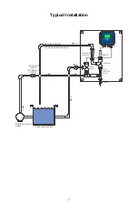
A “U” trap should be installed so that if the flow stops, the sensor is still 
immersed in the water. The outlet of the flow cell must be plumbed to open 
atmosphere unless the system pressure is at or below 1 atmosphere. If the 
flow through the line cannot be stopped to allow for cleaning and 
calibration of the sensor, then it should be placed in a by-pass line with 
isolation valves to allow for sensor removal.  Install the sensor vertically, 
with the measuring surface pointing down, at least 5 degrees above 
horizontal. (Refer to Installation drawings) 
 
Flow rate regulation must be done upstream from the sensor, because any 
flow restriction downstream can increase the pressure above atmospheric 
and damage the membrane cap! 
 
The sensor should be installed in an area where there is good solution 
movement and where it will respond rapidly to chemical additions. The 
placement of the sensor relative to the placement of chemical 
replenishment, along with the quality of the mixing, and the replenishment 
chemical flow rate are critical to accurate process control. 
 
To avoid biological growth on the membrane, which can block 
measurement, never leave the sensor in water without oxidant for longer 
than 24 hours. 


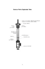
Installing Sensor into Flow Cell 

1.


Assemble the flow cell as shown below from the top down. The reducer 
should already be installed in the flow cell body.  

 
2.


Slide the 103419-B bottom washer (concave side up) over the cable end 
of the sensor, followed by the 103422 O-ring, followed by the 103419-T 
top washer (concave side down), followed by the 102586 nut. 


3.


Place the 102594 O-ring in the top o-ring groove of the 191279-R flow 
cell body. 

 
4.


Place the sensor body into the flow cell body, and tighten the 102586 nut 
until it is hand-tight. Before tightening completely, pull the sensor up 
until the clip ring is up against the bottom washer. 


Содержание WDSW100

Страница 1: ...Five Boynton Road Hopping Brook Park Holliston MA 01746 USA TEL 508 429 1110 WEB www walchem com Disinfection Sensors Instruction Manual...

Страница 2: ...chanical parts and electrodes from date of delivery from the factory or authorized distributor under normal use and service and otherwise when such equipment is used in accordance with instructions fu...

Страница 3: ...ions 8 3 0 Operation 13 Conditioning 13 Calibration 13 4 0 Troubleshooting 15 The disinfectant reading is much lower than the manual analysis 15 The disinfectant reading is much higher than the manual...

Страница 4: ...embrane cap a 100 ml bottle of electrolyte fill solution and special abrasive paper Make sure that all parts are included The oxidizer molecules diffuse through the membrane and in the acidic environm...

Страница 5: ...he rubber band from the groove in the membrane cap just until the vent hole underneath is exposed then fill the membrane cap to the top with the electrolyte fill solution Never shake the electrolyte b...

Страница 6: ...peat several times at different angles Never touch or clean the brown electrode shaft 5 Holding the electrode shaft upright place it onto the filled membrane cap with the mounted G holder You may have...

Страница 7: ...e that the bands are smooth and flush 5 Rinse your hands the sensor and all surfaces contaminated with electrolyte solution with running water Check the sensor for leaks especially at the membrane and...

Страница 8: ...uld be installed in an area where there is good solution movement and where it will respond rapidly to chemical additions The placement of the sensor relative to the placement of chemical replenishmen...

Страница 9: ...iew Disinfection Sensor Washer Set p n 103419 O Ring p n 103422 Nut p n 102586 Cable p n 191303 for WDIS400 WebMaster Cable p n 191655 for W100 W600 Membrane cap Clip Ring groove Clip ring O Ring p n...

Страница 10: ...Typical Installation ISOLATION VALVE NORMALLY OPEN RECIRCULATION PUMP ROTAMETER 30 100 LPH PROCESS WATER SAMPLE RETURN 1 ATMOSPHERE MAXIMUM FLOW SWITCH SENSOR FLOW CELL FLOW CONTROL VALVE SAMPLE VALV...

Страница 11: ...le The wiring to the controller is as follows Shield Drain Earth Ground GRN IN WHT IN RED 5 V BLK 5 V If the required cable length exceeds the 6 meters 20 feet that is supplied wire the housing to a 1...

Страница 12: ...the instrument The maximum cable length is 30 5 meters 100 feet WDIS410 Power Supply 115 VAC or 230 VAC Contact Closure Polarity not critical Interlock Function 5V T T GROUND STUD L1 L2 N G R N 1 2 0...

Страница 13: ...2 1 2 3 4 5 6 7 8 9 10 11 12 13 14 15 16 17 18 1 2 3 4 5 6 7 8 9 10 11 12 13 14 15 16 17 18 1 2 3 4 5 6 7 8 9 10 11 12 13 14 15 16 17 18 TB1 TB4 TB6 TB5 TB7 N N N N N N R1 R2 R3 R4 R5 R6 POWER SWITCH...

Страница 14: ...4 5 6 7 8 9 10 11 12 TB2 TB1 FUSE POWER SW ITCH POWER SWITCH 1 2 3 4 5 6 7 8 9 10 11 12 R1 R2 R3 N N N N L TB3 TB4 TB5 TB6 TB7 pH TB1 1 2 3 4 5 6 7 8 9 10 11 12 5V BLK IN WH T IN GRN SHIELD 5V RED SAF...

Страница 15: ...12 W900...

Страница 16: ...f the application 4 The stability of the sensor and controller as a system The frequency of calibration is really determined by experience At a new installation calibration might initially be checked...

Страница 17: ...14...

Страница 18: ...ions 5 When the reading is stable continue to the final steps of the calibration NOTE Disinfectant concentration can change rapidly in the sample Minimize the time between performing the DPD test or m...

Страница 19: ...ring Check wiring Faulty sensor Replace sensor Faulty controller sensor input Go to the Sensor Input menu and perform a self test If this passes then the problem is with the sensor or its wiring If it...

Страница 20: ...or the appropriate amount of time before attempting a calibration Insufficient sample flow Increase flow rate to between 30 and 100 liters per hour Air bubbles on membrane Dislodge bubbles Adjust flow...

Страница 21: ...ctants on the standard free chlorine bromine sensor membrane as these will reduce the life of the membrane If the sensor still cannot be calibrated after cleaning replace the membrane cap as described...

Страница 22: ...ubmerged in water For long term storage up to 3 years follow this procedure CAUTION Wear gloves and safety glasses during assembly of the sensor since the electrolyte is a STRONG ACID It is recommende...

Страница 23: ...erating Pressure Sensor 0 to 3 atmosphere 0 to 44 psi Total Chlorine CP4 0 to 1 atmosphere 0 to 14 7 psi All other sensors Operating Pressure Optional flow switch 0 to 10 3 atmosphere 0 150 PSI see gr...

Страница 24: ...30 to 100 liters hour 0 13 to 0 44 gal min pH Range 6 8 8 0 pH must be stable within 0 10 Conductivity Range Up to 4 NaCl Response time 30 sec Conditioning time 60 min Free Chlorine Bromine Extended p...

Страница 25: ...l 0 01 mg l 0 200 mg l 0 167 5 mg l 0 100 mg l 0 1 mg l Sensitivity Free Chlorine 5 Ozone 2500 Sample Flow rate 30 to 100 liters hour 0 13 to 0 44 gal min pH Range 1 0 11 0 Conductivity Range No Limi...

Страница 26: ...me 60 min Hydrogen Peroxide Range W100 W600 W900 Range WDIS Range WM1 WIND Resolution 0 200 mg l 0 167 5 mg l 0 100 mg l 0 1 mg l 0 2 000 mg l 0 1 675 mg l 0 1000 mg l 1 mg l 0 20 000 mg l 0 16 750 mg...

Страница 27: ...SOR ClO2 2 PPM 4 20 mA 191648 103462 103475 SENSOR ClO2 5 PPM 4 20 mA 191650 103462 103475 SENSOR H2O2 200 PPM WP7 191537 103462 103761 SENSOR H2O2 2000 PPM WP7 191539 103462 103761 SENSOR H2O2 20000...

Страница 28: ...25...

Отзывы: