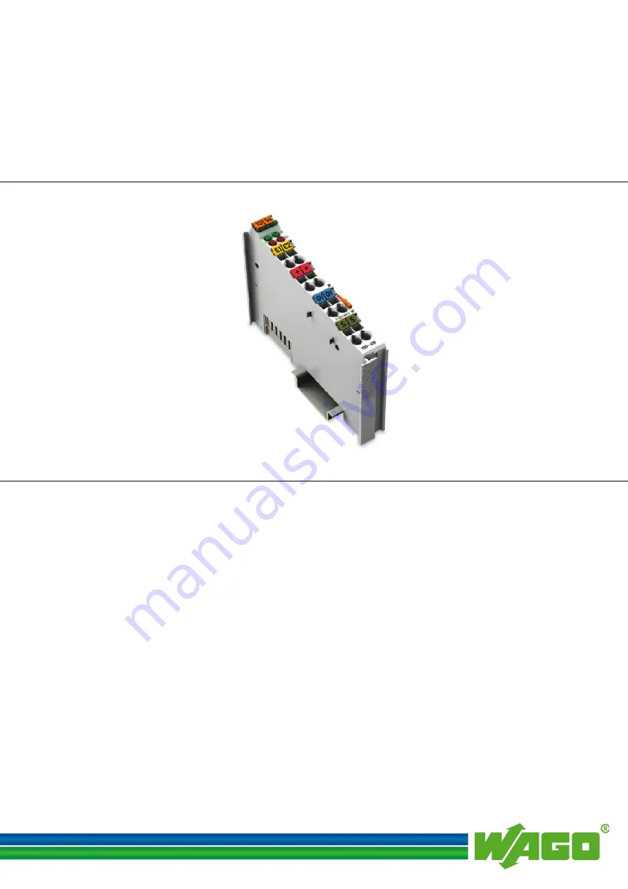
background image

Pos: 2 /Dokumentation allgemein/Einband/Einband Handbuch - Frontseite 2015 - mit DocVariablen (Standard) @ 9\mod_1285229289866_0.docx @ 64941 @  @ 1 


WAGO-I/O-SYSTEM 750 

Manual 


750-476  

2AI ±10V DC S.E.


2-Channel Analog Input Module ±10 V, Single-Ended 


Version 1.1.0 


Pos: 3 /Alle Serien (Allgemeine Module)/Rechtliches, Allgemeines/Impressum für Standardhandbücher - allg. Angaben, Anschriften, Telefonnummern und E-Mail-Adressen @ 3\mod_1219151118203_21.docx @ 21060 @  @ 1 


Содержание WAGO-I/O-SYSTEM 750-476

Страница 1: ...6_0 docx 64941 1 WAGO I O SYSTEM 750 Manual 750 476 2AI 10V DC S E 2 Channel Analog Input Module 10 V Single Ended Version 1 1 0 Pos 3 Alle Serien Allgemeine Module Rechtliches Allgemeines Impressum für Standardhandbücher allg Angaben Anschriften Telefonnummern und E Mail Adressen 3 mod_1219151118203_21 docx 21060 1 ...

Страница 2: ...1 8 87 85 55 E Mail support wago com Every conceivable measure has been taken to ensure the accuracy and completeness of this documentation However as errors can never be fully excluded we always appreciate any information or suggestions for improving the documentation E Mail documentation wago com We wish to point out that the software and hardware terms as well as the trademarks of companies use...

Страница 3: ...ified Devices 10 2 2 Safety Advice Precautions 11 3 Device Description 13 3 1 View 15 3 2 Connectors 16 3 2 1 Data Contacts Internal Bus 16 3 2 2 Power Jumper Contacts Field Supply 17 3 2 3 CAGE CLAMP Connectors 19 3 3 Display Elements 20 3 4 Operating Elements 20 3 5 Schematic Diagram 21 3 6 Technical Data 22 3 6 1 Device Data 22 3 6 2 Power Supply 22 3 6 3 Communication 22 3 6 4 Inputs 22 3 6 5 ...

Страница 4: ...Regulations 39 7 2 1 Special Conditions for Safe Use ATEX Certificate TÜV 07 ATEX 554086 X 40 7 2 2 Special Conditions for Safe Use ATEX Certificate TÜV 12 ATEX 106032 X 41 7 2 3 Special Conditions for Safe Use IEC Ex Certificate TUN 09 0001 X 42 7 2 4 Special Conditions for Safe Use IEC Ex Certificate IECEx TUN 12 0039 X 43 7 2 5 Special Conditions for Safe Use According to ANSI ISA 12 12 01 44 L...

Страница 5: ...ise zur Dokumentation Hinweise Achtung Hinweis zur Dokumentation Busklemmen 750 xxxx 4 mod_1237986979656_21 docx 29023 1 The I O module 750 476 shall only be installed and operated according to the instructions in this manual and in the manual for the used fieldbus coupler controller Consider power layout of the WAGO I O SYSTEM 750 In addition to these operating instructions you will also need the...

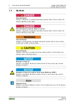
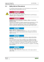
Страница 6: ...os 12 5 4 Alle Serien Allgemeine Module Sicherheits und sonstige Hinweise Vorsicht Vorsicht _Warnung vor Personenschäden allgemein_ Erläuterung 13 mod_1343310028762_21 docx 101038 1 Personal Injury Indicates a low risk potentially hazardous situation which if not avoided may result in minor or moderate injury Pos 12 5 5 Alle Serien Allgemeine Module Sicherheits und sonstige Hinweise Achtung Achtun...

Страница 7: ...2AI 10V DC S E Manual Version 1 1 0 Additional Information Refers to additional information which is not an integral part of this documentation e g the Internet Pos 12 6 Dokumentation allgemein Gliederungselemente Seitenwechsel 3 mod_1221108045078_0 docx 21810 1 ...

Страница 8: ...tions Pos 12 10 Alle Serien Allgemeine Module Rechtliches Allgemeines Schriftkonventionen 3 mod_1221059521437_21 docx 21714 1 Table 2 Font Conventions Font Type Indicates italic Names of paths and data files are marked in italic type e g C Program Files WAGO Software Menu Menu items are marked in bold letters e g Save A greater than sign between two names means the selection of a menu item from a ...

Страница 9: ...50 xxxx Überschrift 3 und Inhalt 3 mod_1224061208046_21 docx 24063 3 1 2 1 2 Personnel Qualifications All sequences implemented on WAGO I O SYSTEM 750 devices may only be carried out by electrical specialists with sufficient knowledge in automation The specialists must be familiar with the current norms and guidelines for the devices and automated environments All changes to the coupler or control...

Страница 10: ...Überschrift 3 und Inhalt 3 mod_1221060446109_21 docx 21723 3 1 2 1 4 Technical Condition of Specified Devices The devices to be supplied ex works are equipped with hardware and software configurations which meet the individual application requirements WAGO Kontakttechnik GmbH Co KG will be exempted from any liability in case of changes in hardware or software as well as to non compliant usage of d...

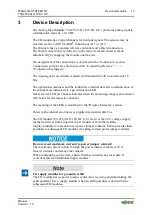
Страница 11: ...gsvorschriften beachten 6 mod_1260180657000_21 docx 46735 1 Pos 15 10 4 Alle Serien Allgemeine Dokumente Allgemeine Module Wichtige Erläuterungen Sicherheitshinweise Gefahr Gefahr Auf normgerechten Anschluss achten 6 mod_1260180753479_21 docx 46739 1 Pos 15 11 1 Alle Serien Allgemeine Dokumente Allgemeine Module Wichtige Erläuterungen Sicherheitshinweise Achtung Achtung Defekte oder beschädigte Ge...

Страница 12: ...nes as this may damage the devices involved Pos 15 11 6 Alle Serien Allgemeine Dokumente Allgemeine Module Wichtige Erläuterungen Sicherheitshinweise Achtung Achtung Elektrostatische Entladung vermeiden 6 mod_1260181364729_21 docx 46759 1 Avoid electrostatic discharge The devices are equipped with electronic components that may be destroyed by electrostatic discharge when touched Please observe th...

Страница 13: ...trieb und Klemmenbus Kommunikation 5 mod_1247054901573_21 docx 36892 1 The operational readiness and the trouble free internal data bus communication of the channels are indicated via a green function LED Pos 18 9 Serie 750 WAGO I O SYSTEM Gerätebeschreibung Einleitung LED Anzeige LED Fehler Bereichsüber unterschreitung 15 mod_1370281145613_21 docx 121530 1 One red error LED per channel indicates ...

Страница 14: ...of potentials is not necessary Pos 18 16 Serie 750 WAGO I O SYSTEM Gerätebeschreibung Einleitung Einsatzbereich Einsatzbereich 750 xxxx alle Koppler Controller ohne Economy Koppler 3 mod_1232541867468_21 docx 26525 1 The I O module 750 476 can be used with all fieldbus couplers controllers of the WAGO I O SYSTEM 750 except for the economy types 750 320 323 324 and 327 Pos 19 Dokumentation allgemei...

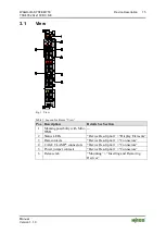
Страница 15: ...GO I O SYSTEM Gerätebeschreibung Ansicht Ansicht CageClamp _Legende mit LEDs mit 1 Entriegelungslasche 15 mod_1370867188922_21 docx 122225 1 Table 3 Legend for Figure View Pos Description Details See Section 1 Marking possibility with Mini WSB 2 Status LEDs Device Description Display Elements 3 Data contacts Device Description Connectors 4 CAGE CLAMP connectors Device Description Connectors 5 Powe...

Страница 16: ...ble as self cleaning gold spring contacts Figure 2 Data Contacts Pos 26 2 Serie 750 WAGO I O SYSTEM Wichtige Erläuterungen Sicherheits und sonstige Hinweise Achtung Achtung Busklemmen nicht auf Goldfederkontakte legen 7 mod_1266318463636_21 docx 50695 1 Do not place the I O modules on the gold spring contacts Do not place the I O modules on the gold spring contacts in order to avoid soiling or scr...

Страница 17: ...takte 2 LK Messer Leistungskontakte 2 LK Messer Feder Abbildung einfache Breite Standard 15 mod_1367500700037_21 docx 118396 1 Figure 3 Power Jumper Contacts Pos 29 4 Serie 750 WAGO I O SYSTEM Gerätebeschreibung Anschlüsse Leistungskontakte 2 LK Messer Leistungskontakte 2 LK Messer Feder Legende 15 mod_1371721352500_21 docx 123710 1 Table 4 Legend for Figure Power Jumper Contacts Contact Type Func...

Страница 18: ...ules for ground earth The I O module has no power jumper contacts for receiving and transmitting the earth potential Use a supply module when an earth potential is needed for the subsequent I O modules Pos 30 Dokumentation allgemein Gliederungselemente Seitenwechsel 3 mod_1221108045078_0 docx 21810 1 ...

Страница 19: ...ignal 24 V 2 Field supply Uv 0 V 3 Field supply 0 V S 4 Shield 2 AI 2 5 Current signal 24 V 6 Field supply Uv 0 V 7 Field supply 0 V S 8 Shield Pos 33 Serie 750 WAGO I O SYSTEM Wichtige Erläuterungen Sicherheits und sonstige Hinweise Hinweis Hinweis Geschirmte Signalleitungen verwenden 7 mod_1265723251019_21 docx 50140 1 Use shielded signal lines Only use shielded signal lines for analog signals a...

Страница 20: ...trouble free internal data bus communication Error AI1 B Off Normal operation Red Overrange underrange of the admissible measuring range 2 Function AI2 C Off Not ready for operation or no or disturbed internal bus communication Green Operational readiness and trouble free internal data bus communication Error AI2 D Off Normal operation Red Overrange underrange of the admissible measuring range Pos...

Страница 21: ...haltbild Überschrift 2 4 mod_1240984441312_21 docx 31967 2 1 3 5 Schematic Diagram Pos 41 Serie 750 WAGO I O SYSTEM Gerätebeschreibung Schematische Schaltbilder Analogeingangsklemmen Schematisches Schaltbild 750 0476 24 mod_1448392412252_21 docx 196175 1 Figure 6 Schematic Diagram Pos 42 Dokumentation allgemein Gliederungselemente Seitenwechsel 3 mod_1221108045078_0 docx 21810 1 ...

Страница 22: ...ge typ internal 75 mA Input voltagemax 24 V Signal voltage 10 V Isolation 500 V system field side 3 6 3 Communication Table 9 Technical Data Communication Data width internal internal data bus 2 16 bit data 2 8 bit control status optional 3 6 4 Inputs Table 10 Technical Data Inputs Number of inputs 2 Connection type Single ended Input voltage measurement range 10 V 10 V Internal resistancetyp 130 ...

Страница 23: ... Überschriften Ebene 3Anschlusstechnik Überschrift 3 17 mod_1380123271324_21 docx 132788 3 1 3 6 6 Connection Type Pos 46 2 Serie 750 WAGO I O SYSTEM Gerätebeschreibung Technische Daten Technische Daten Verdrahtungsebene CC 0 08 bis 2 5mm2 17 mod_1380121238809_21 docx 132780 1 Table 12 Technical Data Field Wiring Wire connection CAGE CLAMP Cross section 0 08 mm 2 5 mm AWG 28 14 Stripped lengths 8 ...

Страница 24: ..._1224662755687_0 docx 24460 1 Pos 52 Alle Serien Allgemeine Module Zulassungen Standardzulassungen KC Korea Certificate AI 20 mod_1406533217893_21 docx 160376 1 Korea Certification MSIP REM W43 AIM750 Pos 53 Dokumentation allgemein Gliederungselemente Leerzeile 3 mod_1224662755687_0 docx 24460 1 Pos 54 Serie 750 WAGO I O SYSTEM Gerätebeschreibung Zulassungen Ex Zulassungen Busklemme 750 xxxx Ex oh...

Страница 25: ...en NKK Nippon Kaiji Kyokai 3 mod_1224493002656_0 docx 24240 1 NKK Nippon Kaiji Kyokai Pos 61 9 Alle Serien Allgemeine Dokumente Allgemeine Module Zulassungen Schiffszulassungen PRS Polski Rejestr Statków 3 mod_1224497273250_0 docx 24295 1 PRS Polski Rejestr Statków Pos 61 10 Alle Serien Allgemeine Dokumente Allgemeine Module Zulassungen Schiffszulassungen RINA Registro Italiano Navale 3 mod_122449...

Страница 26: ...WAGO I O SYSTEM Prozessabbild Klemmenbus Analogeingangsklemmen Prozessabbild 750 0476 5 mod_1251801974890_21 docx 41228 2 1 4 1 Standard Format For the 750 476 I O module the input voltage range of 10 V 10 V is scaled to the numerical range of 0x8000 0x7FFF Table 15 Process Image Input voltage 10 V Numeric value Status Byte Hex LED Error AI 1 2 Binary Measured value Hex Dec 11 0 1000 0000 0000 000...

Страница 27: ...Verletzungsgefahr durch scharfkantige Messerkontakte 6 mod_1256193279401_21 docx 43414 1 Risk of injury due to sharp edged blade contacts The blade contacts are sharp edged Handle the I O module carefully to prevent injury Pos 75 3 Serie 750 WAGO I O SYSTEM Wichtige Erläuterungen Sicherheits und sonstige Hinweise Achtung Achtung Busklemmen nur in vorgesehener Reihenfolge stecken 6 mod_125619417707...

Страница 28: ...8 Serie 750 WAGO I O SYSTEM Montieren Demontieren Busklemme einfügen 3 mod_1231769726703_21 docx 25989 3 1 5 2 1 Inserting the I O Module 1 Position the I O module so that the tongue and groove joints to the fieldbus coupler controller or to the previous or possibly subsequent I O module are engaged Figure 7 Insert I O Module Example 2 Press the I O module into the assembly until the I O module sn...

Страница 29: ...9375203_21 docx 30334 3 1 5 2 2 Removing the I O Module 1 Remove the I O module from the assembly by pulling the release tab Figure 9 Removing the I O Module Example Electrical connections for data or power jumper contacts are disconnected when removing the I O module Pos 76 Dokumentation allgemein Gliederungselemente Seitenwechsel 3 mod_1221108045078_0 docx 21810 1 ...

Страница 30: ...tors Only connect one conductor to each CAGE CLAMP Only one conductor may be connected to each CAGE CLAMP Do not connect more than one conductor at one single connection If more than one conductor must be routed to one connection these must be connected in an up circuit wiring assembly for example using WAGO feed through terminals 1 For opening the CAGE CLAMP insert the actuating tool into the ope...

Страница 31: ...9_21 docx 50140 1 Use shielded signal lines Only use shielded signal lines for analog signals and I O modules which are equipped with shield clamps Only then can you ensure that the accuracy and interference immunity specified for the respective I O module can be achieved even in the presence of interference acting on the signal cable Pos 82 Serie 750 WAGO I O SYSTEM Anschließen Anschlussbeispiele...

Страница 32: ... 750 3 mod_1234272230203_21 docx 27500 1 The WAGO I O SYSTEM 750 electrical equipment is designed for use in Zone 2 hazardous areas The following sections include both the general identification of components devices and the installation regulations to be observed The individual subsections of the Installation Regulations section must be taken into account if the I O module has the required approv...

Страница 33: ...n Ex Bereichen Kennzeichnung für Europa gemäß ATEX und IEC EX Überschrift 3 3 mod_1224157620203_21 docx 24185 3 1 7 1 1 Marking for Europe According to ATEX and IEC Ex Pos 84 6 Serie 750 WAGO I O SYSTEM Einsatz in Ex Bereichen Beispielbedruckung der ATEX und IEC Ex zugelassenen Busklemmen gemäß CENELEC und IEC_2013 14 mod_1360569228625_21 docx 111294 1 Figure 12 Side Marking Example for Approved I...

Страница 34: ...roup Mining M2 Category High level of protection Ex Explosion protection mark d Mb Type of protection and equipment protection level EPL Flameproof enclosure I Explosion group for electrical equipment for mines susceptible to firedamp Gases II Equipment group All except mining 3G Category 3 Zone 2 Ex Explosion protection mark nA Gc Type of protection and equipment protection level EPL Non sparking...

Страница 35: ...nsatz in Ex Bereichen Beispielbedruckung der Ex i und IEC Ex i zugelassenen Busklemmen gemäß CENELEC und IEC_2013 14 mod_1360569320118_21 docx 111298 1 Figure 14 Side Marking Example for Approved Ex i I O Modules According to ATEX and IECEx Figure 15 Text Detail Marking Example for Approved Ex i I O Modules According to ATEX and IECEx ...

Страница 36: ...ection level EPL protection by enclosure ia Da Type of protection and equipment protection level EPL associated apparatus with intrinsic safety circuits for use in Zone 20 ib Db Type of protection and equipment protection level EPL associated apparatus with intrinsic safety circuits for use in Zone 21 IIIC Explosion group of dust T 135 C Max surface temperature of the enclosure without a dust laye...

Страница 37: ...or a category 2 Zone 1 equipment Ex Explosion protection mark nA Gc Type of protection and equipment protection level EPL Non sparking equipment ia Ga Type of protection and equipment protection level EPL associated apparatus with intrinsic safety circuits for use in Zone 0 ia Gb Type of protection and equipment protection level EPL associated apparatus with intrinsic safety circuits for use in Zo...

Страница 38: ...emäß NEC 500_2013 14 mod_1360580302684_21 docx 111353 1 Figure 16 Side Marking Example for I O Modules According to NEC 500 Figure 17 Text Detail Marking Example for Approved I O Modules According to NEC 500 Table 18 Description of Marking Example for Approved I O Modules According to NEC 500 Printing on Text Description CL I Explosion protection group condition of use category DIV 2 Area of appli...

Страница 39: ...ions Pos 84 14 Alle Serien Allgemeine Module Einsatz in Ex Bereichen Errichtungsbestimmungen Einleitung_2013 14 mod_1360582328318_21 docx 111371 1 For the installation and operation of electrical equipment in hazardous areas the valid national and international rules and regulations which are applicable at the installation location must be carefully followed Pos 84 15 Dokumentation allgemein Glied...

Страница 40: ...nd potentiometers connected to the module may only be actuated when explosive atmosphere can be excluded 4 The connecting and disconnecting of the non intrinsically safe circuits is only permitted during installation for maintenance or for repair purposes The temporal coincidence of explosion hazardous atmosphere and installation maintenance resp repair purposes shall be excluded This is although ...

Страница 41: ... a sufficient protection according to EN 60079 0 and EN 60079 1 and the degree of protection IP64 The compliance of these requirements and the correct installation into an enclosure or a control cabinet of the devices shall be certified by an ExNB 2 Measures have to be taken outside of the device that the rating voltage is not being exceeded of more than 40 because of transient disturbances 3 The ...

Страница 42: ...potentiometers connected to the module may only be actuated when explosive atmosphere can be excluded 4 The connecting and disconnecting of the non intrinsically safe circuits is only permitted during installation for maintenance or for repair purposes The temporal coincidence of explosion hazardous atmosphere and installation maintenance resp repair purposes shall be excluded This is although and...

Страница 43: ...sufficient protection according to IEC 60079 0 and IEC 60079 1 and the degree of protection IP64 The compliance of these requirements and the correct installation into an enclosure or a control cabinet of the devices shall be certified by an ExCB 2 Measures have to be taken outside of the device that the rating voltage is not being exceeded of more than 40 because of transient disturbances 3 The c...

Страница 44: ...conomy bus modules only The instructions shall contain the following The configuration interface Service connector is for temporary connection only Do not connect or disconnect unless the area is known to be non hazardous Connection or disconnection in an explosive atmosphere could result in an explosion I Modules containing fuses only WARNING Devices containing fuses must not be fitted into circu...

Страница 45: ...Example 29 Figure 10 Connecting a Conductor to a CAGE CLAMP 30 Figure 11 Connection Example 31 Figure 12 Side Marking Example for Approved I O Modules According to ATEX and IECEx 33 Figure 13 Text Detail Marking Example for Approved I O Modules According to ATEX and IECEx 33 Figure 14 Side Marking Example for Approved Ex i I O Modules According to ATEX and IECEx 35 Figure 15 Text Detail Marking Ex...

Страница 46: ... Supply 22 Table 9 Technical Data Communication 22 Table 10 Technical Data Inputs 22 Table 11 Technical Data Climatic Environmental Conditions 23 Table 12 Technical Data Field Wiring 23 Table 13 Technical Data Power Jumper Contacts 23 Table 14 Technical Data Data Contacts 23 Table 15 Process Image 26 Table 16 Description of Marking Example for Approved I O Modules According to ATEX and IECEx 34 Ta...

Страница 47: ...WAGO I O SYSTEM 750 List of Tables 47 750 476 2AI 10V DC S E Manual Version 1 1 0 Ende der Liste für Textmarke Verzeichnis_hinten ...

Страница 48: ...te 2015 9 mod_1285229376516_21 docx 64944 1 WAGO Kontakttechnik GmbH Co KG Postfach 2880 D 32385 Minden Hansastraße 27 D 32423 Minden Phone 05 71 8 87 0 Fax 05 71 8 87 1 69 E Mail info wago com Internet http www wago com Ende der Liste für Textmarke Einband_hinten ...

Отзывы: