Serie 750, 753
Planning
System manual | Version: 3.0.2
35
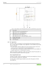
Example of a Power Supply Concept for Marine Applications - Class A and B per
DNV GL
U
S
U
F1
U
F2
1
2
3
4
U
F3
5
Figure 16: Power Supply Concept for Marine Applications – Class A and B
1
Filter module, 24 VDC, HI GF (750-626/020-002) or
filter module, 24 VDC, HI (750-626/020-000) or
filter module, 24 VDC, HI / T (750-626/025-001)
2
Bus supply module, 24 VDC (750-602) or
bus supply module, 24 VDC, with fuse (750-601) or
bus supply module, 24 VDC, with fuse and diagnostics (750-610)
3
Filter module, 24 VDC, HI GF 750-624/020-002 or
filter module, 24 VDC, HI 750-624/020-000
4
Distance module, 24 VDC / 230 VAC (750-616/030-000)
5
Bus supply module, 230 VAC/DC, with diagnostics, with fuse holder (750-611) or
bus supply module, 230 VAC/DC, without diagnostics, with fuse holder (750-609) or
bus supply module, 230 VAC/DC, without diagnostics, without fuse holder (750-612)
U
S
System supply (24 VDC)
U
F1
Field supply 1 (24 VDC)
U
F2
Field supply 2 (24 VDC)
U
F3
Field supply 3 (230 VAC)
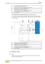
Power Supply with FE Power Jumper Contact
If an FE power contact is required after the filter module (750-626/xxx-xxx), an additional
supply module is required after the filter module. To do this, the field supply from the filter
module (750-626/xxx-xxx) must be bridged to the supply module.

