background image

5

ProSpray 20


GB

d) Store unused power tools so that they are inaccessible 

to children. Do not let persons use the tool who 

are not familiar with it or who have not read these 

instructions. 

Power tools are dangerous when they are used 

by inexperienced persons.


e) Maintain the power tool and insertion tools with 

care. Check whether moving device parts are working 

flawlessly and are not jamming, whether parts are 

broken or damaged so that as to impair the function 

of the power tool. Have damaged parts repaired before 

using the power tool. 

Many accidents have their origin in 

power tools that have been maintained badly.


f) Use the power tool, accessories, insert tools, etc. in 

accordance with these instructions and in a fashion 

specified for this special tool type. Take the working 

conditions and the activity to be carried out into 

consideration. 

The use of power tools for purposes other 

than the intended ones can lead to dangerous situations.


g) Keep the handles and grip surfaces dry, clean and free 

of oil and grease.

 Slippery handles and grip surfaces 

hamper safe operation and control of the electric tool in 

unforeseen situations.

5. Service 

a) Only have your power tool repaired by a qualified 

specialist and only use original spare parts. 

This 

ensures that the tool safety is maintained.


b) If the supply cord is damaged, it must be replaced 

by the manufacturer or it’s service agent or a 

similarly qualified person in order to avoid a safety 

hazard.

SAFETY REGULATIONS FOR 
AIRLESS SPRAYING

All local safety regulations in force must be observed.

The following safety regulations are to be observed in order to 

ensure safe handling of the Airless high-pressure spraying unit.

2.1 

FLASH POINT

Only spray coating materials with a flash point 

of 21 °C or higher.

The flash point is the lowest temperature at 

which vapors develop from the coating mate-

rial. These vapors are sufficient to form an in-

flammable mixture over the air above the coat-

ing material.

2.2 

EXPLOSION PROTECTION

Do not use the unit in work places which are 

covered by the explosion protection regula-

tions. The unit is not designed to be explosion 

protected. Do not operate the device in ex-

plosive areas (zone 0, 1 and 2). Explosive ar-

eas are, for example, places where paints are 

stored and locations in direct proximity to the 

object being sprayed. Keep the device at least 

3 m from the object you are spraying.

2.3 

DANGER OF EXPLOSION AND FIRE FROM 

SOURCES OF IGNITION DURING SPRAYING 

WORK

There must be no sources of ignition such as, 

for example, open fires, lit cigarettes, cigars or 

tobacco pipes, sparks, glowing wires, hot sur-

faces, etc. in the vicinity.

2.4 

DANGER OF INJURY FROM THE SPRAY JET

Attention, danger of injury by injection!

Never point the spray gun at yourself, other 

persons or animals.

Only use the spray gun with spray jet touch 

protection.

The spray jet must not come into contact 

with any part of the body.

In working with Airless spray guns, the high 

spray pressures arising can cause very dan-

gerous injuries. If contact is made with the 

spray jet, coating material can be injected 

into the skin. Do not treat a spray injury as a 

harmless cut. In case of injury to the skin by 

coating material or solvents, consult a doctor 

for quick and correct treatment. Inform the 

doctor about the coating material or solvent 

used.

2.5 

SECURE SPRAY GUN AGAINST UNINTENDED 

OPERATION

Always secure the spray gun when mounting or dismounting 

the tip and in case of interruption to work.

2.6 

RECOIL OF SPRAY GUN

When using a high operating pressure, pull-

ing the trigger guard can effect a recoil force 

up to 15 N.

If you are not prepared for this, your hand can 

be thrust backwards or your balance lost. This 

can lead to injury.

Содержание PROSPRAY 20

Страница 1: ...Service manual with electrical repair instructions for electri cally instructed persons of the J Wagner GmbH 2406804 A 07 2019 ProSpray 20...

Страница 2: ......

Страница 3: ...ions____________________________ 22 1 4 Which tests must be performed_________________ 22 1 5 Five safety rules______________________________ 23 1 6 Categorisation of protection classes_____________ 2...

Страница 4: ...doing and worksensiblywithapowertool Donotusethepower tool if you are tired or under the influence of drugs alcoholormedication Onemomentofcarelessnesswhen using the power tool may cause serious inju...

Страница 5: ...he flash point is the lowest temperature at which vapors develop from the coating mate rial These vapors are sufficient to form an in flammable mixture over the air above the coat ing material 2 2 EXP...

Страница 6: ...cloth to wipe down the outside of the hose Lay the high pressure hose in such a way as to ensure that it cannot be tripped over Only use WAGNER original high pressure hoses in order to ensure function...

Страница 7: ...high pressure steam cleaners 2 18 WORK OR REPAIRS AT THE ELECTRICAL EQUIPMENT These may only be carried out by a skilled electrician No lia bility is assumed for incorrect installation Unplug the pow...

Страница 8: ...oor 4 REPAIRS AT THE UNIT Switch the unit OFF Before all repair work Unplug the power plug from the outlet 4 1 RELIEF VALVE Attention The valve housing 4 should not be repaired If worn it should alway...

Страница 9: ...6 9 Clean all the parts with the corresponding cleaning agent Check the inlet valve housing 1 inlet valve seat 5 and inlet valve ball 4 for wear and replace the parts if necessary If the worn inlet v...

Страница 10: ...Push installation tool included with the replacement packings for the piston 3 from above onto the piston 14 Lubricate installation tool and piston 3 with machine grease 15 Guide piston 3 through the...

Страница 11: ...fully tap on the front of the motor crankshaft that extends through the slider assembly 10 With the motor removed inspect the gears in the gear box housing for damage or excessive wear Replace the gea...

Страница 12: ...sure the thrust washer 9 is in place i Refill the gear box in the pump housing with five ounces of Lubriplate GR132 P N 0293396 1 2 3 4 6 7 8 9 5 4 7 REPLACING THE TRANSDUCER 1 Open the relief valve...

Страница 13: ...13 ProSpray 20 GB...

Страница 14: ...54 Washer 11 2409 555 Sevice Set Druckregler 12 2406859 Face plate incl 4 screws 13 2406860 Service Set Prime Spray switch 14 730 197 Cap 15 193 200 Return tube fitting 16 704 117 Screw 2 17 2383 995...

Страница 15: ...15 ProSpray 20 17 1 14 15 16 2 3 7 10 8 9 4 2 3 21 22 23 25 24 20 18 19 6 5 11 12 13 0558 465 220V 240V 6 m CEE 7 7 0532 253 110V 6 m BS4343 GB...

Страница 16: ...ousing 6 227 006 Fitting 7 0507 690 Bypass valve assembly 8 0507 745 Gasket 10 0509 151 Service Set piston 15 762 137 Inlet valve seat 16 0551 533 Service Set consits of item 2 3 9 11 12 13 14 16 17 0...

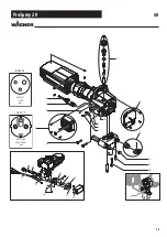
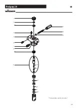
Страница 17: ...17 ProSpray 20 17 18 19 1 2 3 4 6 5 7 8 10 9 11 12 13 14 15 16 Only available as part of a Service Set GB...

Страница 18: ...ankshaft assembly 4 704 176 2nd stage gear 5 0558 314A 0558 353A Motor assembly 230V Motor assembly 110V 6 2409 556 Service Set 4 screws and 4 washers 7 0508 208 Slider assembly 8 9850 936 Switch 9 05...

Страница 19: ...100 Capacitor assembly 230V Capacitor assembly 110V 2 0551174A 0551 540 Motor 230V Motor 110V 0532278A Circuit board 704 276 Motor brush kit 5 4 MOTOR ASSEMBLY Order number for 1 piece Quantities in...

Страница 20: ...STAND ASSEMBLY Part No Description 1 2406 861 Leg left incl item 3 2 2406 862 Leg right incl item 3 3 9885 546 Plug 3 1 3 2 Order number for 1 piece Quantities in brackets indicate the total number i...

Страница 21: ...cludes items 1 8 2 0558659A Return tube 3 0279459 Clip 4 0295565 Inlet screen 5 9871105 O ring 2 704 109 O ring for hot solvents optional 2 6 9822526 Retaining clip 7 9850638 Tie wrap 8 0327226 Return...

Страница 22: ...s and special features The work instructions must include safe and correct replace ment of a connecting cable for example 1 2 SKILLED ELECTRICIAN FOR DEFINED TASKS In order to autonomously carry out w...

Страница 23: ...be disconnected at all poles at the place of work before starting work This can be done by means of main switches expert removal of fuses disconnection of plug connectors etc Protecting against resta...

Страница 24: ...ddition to the basic insulation Connection to the protective conductor system is not possible Appliances with this protection class are not permitted in Germany and Austria This protection class will...

Страница 25: ...n L1 External conductor L2 External conductor L3 External conductor N Neutral conductor PE Protective conductor 3 Threephase AC voltage 1 8 EXPLANATION OF ELECTRICAL TERMS Rated current The rated curr...

Страница 26: ...earthed conductor which performs the function of protective conductor and neutral conductor simulta neously Active part of an electrical system An active part is a live part of an electrical system o...

Страница 27: ...ective 7 The defective component must be made inoperative in order to prevent further use 2 2 FUNCTIONAL TEST OF THE CAPACITOR 1 Ensure safe isolation from the supply before commencing work 2 An insul...

Страница 28: ...heck the electrical functionality If a multimeter is used it should be set to V or VAC 5 Now check the voltage present between L1 and N If this is 230 V AC then the voltage between L1 and PE must also...

Страница 29: ...Note down the connection plan 4 Measure all cables to the housing if a continuity is found then the motor has an earth fault and is defective 5 Measurement of the individual windings is not possible...

Страница 30: ...BGV A3 must be carried out in order to ensure electrical safety and functionality See chapter 1 4 3 3 REPLACING THE CAPACITOR 1 Ensure safe isolation from the supply before commencing work 2 Remove t...

Страница 31: ...the motor protecting switch 4 The motor protecting switch can now be removed 5 Now install the new motor protecting switch and restore the electrical connection 6 After completing the repair a measure...

Страница 32: ...nment 3 Now replace the motor 4 Observe the pin assignment noted in point 2 when connecting the individual wires Also ensure secure contact when con necting the wires 5 After completing the repair a m...

Страница 33: ...OSPRAY 20 MB FB MB FB M F M F M F F F F F F 1 2 3 4 M F F WH6 WH1 WH2 WH7 WH4 WH5 Red Red Blue Blue Brown black Blue white Brown black Blue white Motor EMI filter Microswitch Power cord Switch Capacit...

Отзывы: