20
PowerPainter 90 EXTRA
GB
i
For reasons of function, safety and durability, only use genuine WAGNER high-pressure hoses and spray
nozzles. For overview see „Spare parts lists“.
i
The risk of damage rises with the age of the high-pressure hose.
Wagner recommends replacing high-pressure hoses after 6 years.
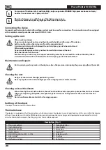
Connecting the device
A properly earthed socket outlet with earthing contact must be used for connection. The connection must be equipped
with a residual current protective device with INF ≤ 30 mA.
Setting up the unit
Danger
When working indoors:
Vapors containing solvents may not be allowed to build up in the area of the device.
Setting up the unit on the side a way from the sprayed object.
A minimum distance of 5 m between the unit and spray gun is to be maintained.
When working outdoors:
Vapors containing solvents may not be allowed to blow toward the unit.
Note the direction of the wind.
Set the unit up in such a way that vapors containing solvents do not reach the unit and build up there.
A minimum distance of 5 m between the unit and spray gun is to be maintained.
Maintenance and repairs
Danger
Before carrying out any work on the device, relieve the pressure and unplug the power plug from the socket.
Cleaning the unit
Danger
Danger of short circuit through penetrating water!
Never spray down the unit with high-pressure or high-pressure steam cleaners.
Cleaning units with solvents
Danger
When cleaning the unit with solvents, the solvent should never be sprayed or pumped back into a container
with a small opening (bunghole). An explosive gas/air mixture can be produced. The container must be
earthed.
Do not use flammable materials for cleaning purposes.
Earthing of the object
The object to be coated must be earthed.
Thermal release
The device is equipped with a thermal release which disconnects the device in case of overheating.
In this case switch the device
off, turn the selector switch to the PRIME position (vertical), remove the mains plug and allow device to cool down for min. 30
minutes. Eliminate the cause of heating, e.g. slots for air intake covered.
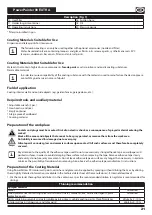
Description (Fig. 1)
1 Pressure regulator
2 Hose connection
3 Inlet valve pusher
4 Hose holder
5 Telescopic handle
6 Spray Gun
7 Nozzle holder
8 Nozzle 517
9 ON / OFF Switch (0 = OFF, I = ON)
10 Selector switch
11 Filter (white)*
12 Tool box
13 High-pressure hose
14 Return line
Содержание POWERPAINTER 90 EXTRA
Страница 1: ...wagner group com D GB NL F I E P DK S RU POWERPAINTER 90 EXTRA ORIGINAL BETRIEBSANLEITUNG...
Страница 3: ...PowerPainter 90 EXTRA l A SPRAY PRIME SPRAY PRIME PRIME SPRAY B C A B O SPRAY PRIME 2 3 1 A B 1...
Страница 4: ...PowerPainter 90 EXTRA 25 30 cm A B C 25 35 cm 25 30 cm 25 30 cm D 1 2 3...
Страница 5: ...PowerPainter 90 EXTRA 1 4 3 2 1 2 3 4 1 8 7 4 10 5 6 11 3 1 2 9 1...
Страница 139: ...133 PowerPainter 90 EXTRA RUS 1 2 3 4 5 1 2 1 2 3 3...
Страница 140: ...134 PowerPainter 90 EXTRA RUS WAGNER i 1 a b c 2 a b c d e...
Страница 141: ...135 PowerPainter 90 EXTRA RUS f 3 a b c d e f g 4 a b c d e f g 5 a b...
Страница 142: ...136 PowerPainter 90 EXTRA RUS 15 200 20...
Страница 143: ...137 PowerPainter 90 EXTRA RUS A 20 197 60 i Wagner i Wagner 6 INF 30 5 5...
Страница 144: ...138 PowerPainter 90 EXTRA RUS PRIME 30 1 1 2 3 4 5 6 7 8 517 9 O I 10 11 12 13 14 15 16 17 18 19 20 i i Wagner...
Страница 145: ...139 PowerPainter 90 EXTRA RUS 2 i PowerPainter 90 1 5 10 0 10 i 1 2 2 3 3 4 4 5 5 6 6 7 7 7 B 8 8 1 9 8 10 9...
Страница 152: ...146 PowerPainter 90 EXTRA RUS ON I SPRAY PRIME 30 PRIME SPRAY PRIME PRIME SPRAY...
Страница 153: ...147 PowerPainter 90 EXTRA RUS 3 1 36 12 4 www wagner group com 3plus1 12 1000 Wagner 14 Wagner...


