distribuidor de corriente de carga
Conexión
33
5.2
Functional description for CoolAir roof air conditioners
– Please also refer to the circuit diagrams on página 7 –
The light system voltage U
D+
is measured. If the voltage exceeds a variable voltage value
Ue (12.5 V - 14.0 V), the 30/87 relay contact of the power relay is closed. The starter
battery and the additional battery are therefore connected in parallel with low ohms and
are charged together by the light system.
Note
A 2-wire sensing cable (included with the CA-DC, item no.: 4441300084) is
used to connect the CA-1000 roof air conditioner (see fig. 6, página 7) to the
ECL-75 charging current distributor (contacts I2 and I3).
Contact I2 is connected to I3 with U
D+
> Ue. If the light system voltage falls below a
variable threshold value Ua (10.5 V - 12.5 V), due to an increased load due to the roof air
conditioner, relay contact 30/87 is opened. Relay contact I2, I3, is also opened and
switches the compressor off (fan keeps running). If the light system voltage exceeds the
set Ue value with U
D+
> Ue, the compressor switches on again automatically.
6
Conexión
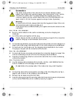
La sección del cable empleado para unir la batería de arranque, el relé de
potencia y la batería de los consumidores no debe ser inferior a 16 mm
2
en el
caso del ECL-75 o a 25 mm
2
en el caso del ECL-100. El cable que une el polo
negativo de la batería de los consumidores con el chasis del vehículo también
debe presentar por lo menos 16 mm
2
o 25 mm
2
(si fuera necesario, recámbielo
por uno de mayor sección).
¡Advertencia!
Debido al peligro de cortocircuito existente, antes de trabajar en el vehículo
desemborne siempre el polo negativo del sistema eléctrico.
Desemborne también el polo negativo en aquellos vehículos con baterías de
refuerzo.
ECL-75/100 – EC-1500/2000:
➤
Tienda el cable de mando desde el acondicionador de aire tipo techo hasta el distri-
buidor de corriente de carga.
➤
Corte el extremo de cable que tiene la clavija.
Cerciórese de que el extremo de cable cortado sea suficientemente largo para
la conexión entre el distribuidor de corriente de carga y el inversor de onda
sinusoidal.
➤
Conecte el cable de mando aislado de dos hilos a los contactos I1 a I4 del distribuidor
de corriente de carga de acuerdo con lo indicado en el esquema de conexiones de
la página 3 (EC-1500), página 4 (EC-2000).
➤
Conecte el distribuidor de corriente de carga con el inversor de onda sinusoidal em-
pleando el extremo de cable cortado. La clavija se atornilla a la conexión del inversor
de onda sinusoidal.
_ECL-75_100.book Seite 33 Freitag, 22. Juli 2005 5:01 17
Содержание Mobitronic ECL-100
Страница 7: ...ECL 75 ECL 100 7 5 6 _ECL 75_100 book Seite 7 Freitag 22 Juli 2005 5 01 17...
Страница 77: ...Latausvirranjakaja Tekniset tiedot 77 _ECL 75_100 book Seite 77 Freitag 22 Juli 2005 5 01 17...
Страница 78: ..._ECL 75_100 book Seite 78 Freitag 22 Juli 2005 5 01 17...
Страница 79: ..._ECL 75_100 book Seite 79 Freitag 22 Juli 2005 5 01 17...

