


Operation
G 150 / 180 / 240
wc_tx000867gb.fm
48
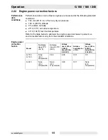
2.30
Remote/transfer switch
Background
A transfer switch is designed to transfer electrical loads from the normal power
source (utility) to the emergency power source (generator) when normal voltage
falls below a prescribed level.
The transfer switch automatically returns the load back to the normal source when
power is restored back to operating levels.
Precautions
Installation of a transfer switch or other type of remote starting device is the
responsibility of the generator user.
Installation of such devices must be performed by a qualified electrician
following all directions supplied by the manufacturer of the switch.
If attaching the generator to a power supply normally serviced by a utility
company, notify the utility company and check local and state regulations.
Familiarize yourself with all instructions and warning labels supplied with the
switch.
WARNING
Electrocution hazard. Failure to isolate the generator from the utility’s electrical
distribution system could cause output from the generator to backfeed into the
utility lines and cause injury or death to utility workers!
f
When the generator is used as a standby power supply, it must be equipped
with a device which isolates it from the utility’s distribution system.
f
An isolation device is also required if the generator is being used as a backup to
some other type of power supply system.
CAUTION!
Possibility of injury or equipment damage. Failure to match phase rotation and
voltage may cause equipment connected to the generator to operate incorrectly.
f
When using the generator as a standby or substitute power supply, make sure
the voltage and phase rotation of the line connections match those of the utility
lines or of any other power source normally used.
DANGER
Electrocution hazard. Lethal voltage is always present in the transfer switch once it
has been properly installed.
f
Disconnect power before servicing the transfer switch.
Содержание G 150
Страница 1: ...Mobile Generator G 150 G 180 G 240 OPERATOR S MANUAL 0171953en 003 0709 0 1 7 1 9 5 3 E N ...
Страница 2: ......
Страница 4: ...Foreword G 150 180 240 wc_tx000869gb fm 4 ...
Страница 12: ...Safety Information G 150 180 240 wc_si000265gb fm 12 wc_si000265gb fm 12 1 6 Label Locations ...
Страница 13: ...G 150 180 240 Safety Information wc_si000265gb fm 13 wc_gr005517 G H J R GG FF R A H K ...
Страница 22: ...Operation G 150 180 240 wc_tx000867gb fm 22 2 2 Control Panel wc_gr005090 m n u d e a t b f h c g j o l k ...
Страница 63: ...Factory Installed Options wc_tx000880gb fm 63 Notes ...
Страница 64: ...Schematics G 150 180 240 wc_tx000879gb fm 64 5 Schematics 5 1 DC Schematic G 150 G 180 G 240 wc_gr005459 ...


