background image

1-6

OM 75Z3/8003 US – Edition 4.0 * * 7003b110.fm

Introduction

1.4

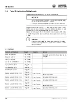
Fields Of Application of Attachments

The attachments will decide in the first place how the machine is used.

NOTICE

In order to avoid damage to the machine, only the attachments listed below 
have been certified for installation on the machine.

• Contact your Wacker Neuson dealer if you wish to use other attachments.

Using attachments of other manufacturers, or tools which have been released for other 
machine types, can reduce the machine’s output and stability considerably, and can also 
cause damage to the machine and injuries to the operator or the staff.
Always compare the weight of the attachment and its maximum payload with the indica-
tions in the lift capacity table. Never exceed the maximum payload stated in the lift capac-
ity table.

Important

Please refer to the Operator’s and maintenance manual of the attachment 
manufacturer for using and performing maintenance on attachments such as 
hammers, grabs etc.

Use: attachment

Description of attachment

Weight

Capacity

Remarks

Mechanical quickhitch

73 kg (161 lbs)

Required for operation of the Wacker Neuson quickh-

itch system

Easy Lock quickhitch

85 kg (187 lbs)

Hammer mount NE36

65 kg (143 lbs)

Universal mount NE36/NE42 

61 kg (134 lbs)

Hydraulic hammer NE36

350 kg (772 lbs)

Hydraulic hammer NE42

438 kg (966 lbs)

Powertilt with Easy Lock

231 kg (509 lbs)

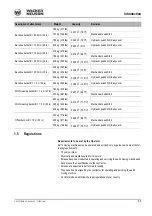
Backhoe bucket B = 300 mm (12 in)

137 kg (302 lbs)

0.096 m

3

 (3.4 ft³)

100 kg (287 lbs)

Mechanical quickhitch

Backhoe bucket B = 350 mm (14 in)

141 kg (298 lbs)

0.127 m

3

 (4.5 ft³)

Hydraulic quickhitch (Easy Lock)

Backhoe bucket B = 400 mm (16 in)

144 kg (317 lbs)

0.148 m

3

 (5.2 ft³)

Hydraulic quickhitch (Easy Lock)

Backhoe bucket B = 450 mm (18 in)

160 kg (353 lbs)

0.154 m

3

 (5.4 ft³)

156 kg (344 lbs)

Mechanical quickhitch

Backhoe bucket B = 500 mm (20 in)

161 kg (355 lbs)

0.183 m

3

 (6.5 ft³)

Hydraulic quickhitch (Easy Lock)

Содержание 75Z3

Страница 1: ...Track Excavator 75Z3 8003 OPERATOR S MANUAL 1000183705 4 0 0312 1 0 0 0 1 8 3 7 0 5 www wackerneuson com...

Страница 2: ...or other attachments Refer to the specific attachment operator s manual for safe operation Wacker Neuson reserves the right to make product improvement changes during the course of series production o...

Страница 3: ...steps in the recommended order This symbol requires you to perform the activity described Description of the effects or results of an activity This symbol shows the driving direction for better orien...

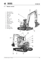
Страница 4: ...work light 3 Undercarriage 4 Stabilizer blade 5 Engine cover 6 Handrail 7 Fuel tank filler inlet 8 Exhaust pipe 9 Lifting tying down point 10 Rotating beacon option 11 Auxiliary hydraulics 12 Tank co...

Страница 5: ...oom stick and bucket The upper structure consists of the following major components or systems Diesel engine pump drive Pressure compensated hydraulic system Operator compartment Control systems for w...

Страница 6: ...s been specially designed for protection in case of an accident ROPS Roll Over Protective Structure tested cab FOPS Falling Object Protective Structure option Do not modify or attempt to repair the RO...

Страница 7: ...e refer to the Operator s and maintenance manual of the attachment manufacturer for using and performing maintenance on attachments such as hammers grabs etc Use attachment Description of attachment W...

Страница 8: ...700 mm 28 in 204 kg 450 lbs 0 256 m3 9 ft Hydraulic quickhitch Easy Lock Backhoe bucket B 750 mm 30 in 216 kg 476 lbs 0 279 m3 9 9 ft 182 kg 401 lbs Mechanical quickhitch Backhoe bucket B 800 mm 32 i...

Страница 9: ...EC and the requirements of further pertinent EC Directives and standards The following standards and or technical specifications have been used for the proper application of the requirements regarding...

Страница 10: ...tive 2006 42 EC appendix XI Fachaussch sse Bau und Tiefbau Pr f und Zertifizierungsstelle im BG PR FZERT Landsberger Str 309 D 80687 Munich Distinguishing EU number 0515 Notified body according to Dir...

Страница 11: ...red sound power level 98 1 dB A Guaranteed sound power level 98 dB A Directives and standards We hereby declare that this product corresponds to the relevant regulations and requirements of the follow...

Страница 12: ...weight poids en charge Operating weight Transportgewicht transport weight poids en transport Transport weight G Gew GWR PTAC Gross weight rating admissible Max Nutzlast max payload max charge utile M...

Страница 13: ...ne number The type label arrow is located on the valve cover engine Hydraulic quickhitch Fig 5 Diesel engine number Fig 5 Diesel engine type label up to serial no AH00610 Fig 5 Diesel engine type labe...

Страница 14: ...ck type label The serial number of the Powertilt is stamped in the housing near the hydraulic connec tions The serial number of the hydraulic quickhitch is located on the type label The type label is...

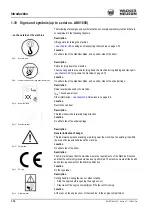
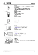
Страница 15: ...ge 6 6 Location Next to the cab door Description This label shows the forward driving direction Location On either side of the undercarriage Description General indication of danger This label warns p...

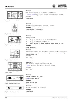
Страница 16: ...iption Add diesel fuel only Location On the fuel tank Description Hydraulic oil reservoir Use only specified hydraulic fluids see chapter 5 21 Fluids and lubricants on page 5 54 Location On the hydrau...

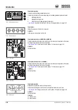
Страница 17: ...s the boom and the stabilizer blade into the ground as you leave the machine remove the starting key and place chocks on the left and right under the tracks see Parking checklist on page 3 19 Location...

Страница 18: ...OM 75Z3 8003 US Edition 4 0 7003b110 fm 1 17 Introduction Description States the pressures that can be measured Location In the engine compartment Fig 28 Measurement ports...

Страница 19: ...1 18 OM 75Z3 8003 US Edition 4 0 7003b110 fm Introduction 1 11 Signs and symbols from serial no AH01659 Overview of adhesive labels...

Страница 20: ...tion Noise levels produced by the machine LWA sound power level see chapter 6 9 Noise levels on page 6 6 Location At the front on the chassis Description This label shows the forward driving direction...

Страница 21: ...49 Control levers control pattern A Overview on page 3 75 Location On the headliner Description from serial no AJ03264 This label describes the pedal and control lever functions control pattern A This...

Страница 22: ...es the proportionally controlled 3rd control circuit and the setting of the control response see chapter Adjusting control response on page 3 83 Location On the headliner Description option This label...

Страница 23: ...l describes the functions of the hydraulic quickhitch see chapter 3 57 Hydraulic quickhitch Easy Lock option on page 3 95 Location On the headliner Description option from serial no AH01659 This label...

Страница 24: ...OM 75Z3 8003 US Edition 4 0 7003b110 fm 1 23 Introduction Safety labels...

Страница 25: ...ne before opening the engine cover Stay clear of the engine compartment if the fan is still running Entanglement hazard You can be pinched or entangled in the engine V belt when the engine is running...

Страница 26: ...er 3 33 Front window from serial no AD06527 on page 3 54 Location On the front window Description Crushing hazard Stay clear of the machine s work range during operation Location On either side of the...

Страница 27: ...ator s Manual and follow the instructions Location On the left hand side on the B pillar in the cab Description Attention Remove starter key and read the Operator s Manual before servicing the machine...

Страница 28: ...safe load indicator must always be switched on during lifting gear applica tions Stay clear of the machine s work range during operation Location Beside the safe load indicator switch on the side wind...

Страница 29: ...ption from Wacker Neuson Retrofitting a fire extinguisher according to NFPA must be performed by an authorized service center Installation in cab Inside the cab at the rear left see figure 65 Importan...

Отзывы:

Похожие инструкции для 75Z3