background image

19

F-001/F-001L

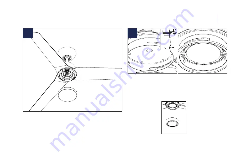
When installing the Non-Luminaire version (F-001)

INSTALLING THE LUMINAIRE MODULE     

11

When installing the Luminaire version (F-001L)

13

12

1.  Install the mounting plate by removing 1 and loosening 

2 screws from the adapter plate and twist-locking the 
mounting plate into place. Twist the cover on - make 
sure it is on tight.

2.  If you purchased F-001 - you are now ready to power on 

your fan.

1.  Attach blue wire from motor to blue wire on LED module and 

white wire from motor to white wire on LED module.

2.  Locate the 3 Luminaire module screws (5/32*8mm Philips 

Head Screws) and install LED module with said screws.

3.  Install PC shade firmly - make sure it is on tight.

Содержание F-001-MW

Страница 1: ...MOCHA Installation Instructions works with the Google Assistant...

Страница 2: ...Please read and review instructions before installation...

Страница 3: ...low when you call For missing parts or general inquiries call our trained technical staff at Model Name and Number Part Number and Part Description Date Of Purchase and Purchase Location Email custome...

Страница 4: ...mum of 1 5 ft 0 5m from the edge of the fan blades to the surrounding walls 5 Never place objects in the path of the fan blades 6 To avoid personal injury or damage to the fan and other items please b...

Страница 5: ...er tools to assemble or install your fan Using power tools can result in improper assembly which can lead to noise or fan dam age personal injury or property damage WARNING To reduce the risk of perso...

Страница 6: ...to 1 ON OFF APP DOWNLOAD Available for purchase on the Google Pay and App Store Quiet reliable and up to 70 more efficient than AC motor fans Wi Fi and Bluetooth enabled for unlimited control Wet loca...

Страница 7: ...Electrical Connections Installing the Optional Wall Control Finishing the Installation Installing the Adapter Plate Installing the Luminaire Module Controlling the Fan Reset App Instructions Accessori...

Страница 8: ...e discarding packaging materials be certain all parts have been removed NOTE Place the parts from the hardware bag into a small container to keep them from being lost MAC ID 03 TOOLS MATERIALS REQUIRE...

Страница 9: ...nectors 8 E LED Module Screw 9 Blade Support Plates x3 F 001L version Canopy Ring RPL CAN RND Adapter Plate Luminaire Cover RPL F001 COVER F 001 version Coupling Cover Hardware Bag RPL F001 PARTS Cano...

Страница 10: ...ashers included with the fan Use PART A if needed 2 Pass supply wires through mounting bracket and secure to outlet box Standard Ceiling Slope Ceiling CAUTION To prevent electrical shock ensure electr...

Страница 11: ...e plastic stoppers from motor housing and discard 2 Place blade on motor assembly hole 3 Secure blade with blade attachment screws washers blade press plates repeat for remaining blades Use Part B ATT...

Страница 12: ...F 001 F 001L 12 4 1 Remove screw from hanger ball Remove hanger ball and cross pin 2 Loosen two screws from coupler remove clevis pin and cotter pin 07 HANGING THE FAN...

Страница 13: ...nrod and motor collar holes re insert pins and screws 2 Slip up canopy and canopy screw cover Re install hanger ball with cross pin in correct place 3 Install coupling cover canopy screw ring canopy a...

Страница 14: ...he United States 2 Slide receiver into place with the flat side facing up 1 Connect the labled wires from fan to the corresponding wires on the receiver 2 Connect the labeled wires from the outlet box...

Страница 15: ...from the wall control to the black LINE VOLTAGE wire from the wall outlet box that feeds back to the circuit breaker 3 Connect the red wire from the wall control to the black wire from the wall outlet...

Страница 16: ...l using the wiring diagram in below 2 Individually pair each of the wall controls with the fan receiver using the pairing instructions in section 15 Wall Control 1 Wall Control 2 Wall Control 3 08 INS...

Страница 17: ...anger Bracket Canopy Canopy Screw Cover FINISHING THE INSTALLATION 09 9 1 Secure wire connectors with supplied wire ties 2 Install canopy to mounting bracket with the screw removed in section 2 3 Inst...

Страница 18: ...HE ADAPTER PLATE 10 11 1 Remove 1 of 3 screws and loosen the others do not remove 1 Twist and lock the adapter plate into place 2 Using the screw from the previous step install the adapter plate Tight...

Страница 19: ...plate and twist locking the mounting plate into place Twist the cover on make sure it is on tight 2 If you purchased F 001 you are now ready to power on your fan 1 Attach blue wire from motor to blue...

Страница 20: ...ptional Wall Control Air Gap Switch only included with wall control Remote Control Unpairing To purge press and hold buttons for 4 seconds NOTE Your fan features 6 speeds An audible tone will indicate...

Страница 21: ...the only limitation being the Bluetooth range of the control and fans you want to have on the same controller Power down the target fans circuit for 30 seconds and then turn it back on Hold the fan an...

Страница 22: ...d all connected fans will beep to indicate the message has been received All lights will turn off This will bring all fans controlled by the remote into sync Fan Direction Press and hold button for 4...

Страница 23: ...set Press and hold buttons for 10 seconds Receiver Factory Reset Press the reset button on the receiver until the receiver beeps FanWi Fi Reset Press and hold the and for 10 seconds until LED blinks g...

Страница 24: ...e WAC app download it from the App Store or Google Play 2 Open the app to create your account You can also log in using your Facebook or Google account 3 To set up a Wi Fi connection you will need the...

Страница 25: ...light to 1 Works in conjunction with WAC Smart Fan receiver not included WT Coupler DC Connects two downrods Slope Ceiling Kit SC Designed to accommodate buildings with steeper sloped ceilings up to 4...

Страница 26: ...l our downrods are 1 1 O D and are threaded on the motor end to create an extra layer of security to allow for adjustments in the field DR18 18 downrod DR24 24 downrod DR36 36 downrod DR48 48 downrod...

Страница 27: ...4 Make sure light cover is tightened and or glass is snug 5 Tighten the hanger bracket screws and make sure the outlet box is secured 6 Your wire connectors may be rattling against the fan s canopy 7...

Страница 28: ...LED indicator remains solid green and three 2 audible beeps are heard the pairing process is complete My home Wi Fi network is not showing up in the app s list during setup 1 Your fan supports connec...

Страница 29: ...g Pairing is the process of connecting your WAC remote or wall control to your fan Your fan comes pre paired to your included remote control However if you want additional controls for your fan or if...

Страница 30: ...WAC Smart Fans est dise ado para facilitarle la vida cada d a WAC crea ventiladores y luminarias para el futuro que proporcionan ahorros de energ a y eficiencia excepcional Nuestra dedicaci n a hacer...

Страница 31: ...i un produit est d fectueux tous les efforts seront d ploy s pour y rem dier Le probl me sur le terrain Si le probl me ne peut pas tre r solu un num ro RGA sera attribu L obligation de WAC est express...

Страница 32: ...waclighting com F 001 F 001L...

Отзывы: