background image

57

www.nieaf-smitt.com

5.12   Frequency (duty cycle) 


1.  Set the rotary function switch to the

 green

 Hz/%  

 position

2.  Insert the black lead banana plug into the negative  


COM jack and the red test lead banana plug into the  


positive Hz jack

3.  Touch the test probe tips to the circuit under test

4.  Read the frequency on the display

5.   Press the MODE button to indicate ‘%’

6.   Read the % duty cycle in the display

5.13   4-20 mA measurement 


1.  Set up and connect as described for DC mA  

 measurements

2.  Set the rotary function switch to the 4-20 mA% position

3.  The meter will display loop current as a % with  


0 mA =-25 %, 4 mA = 0 %, 20 mA = 100 % and  


24 mA = 125 %

Содержание Nieaf Smitt NI 407PLUS

Страница 1: ...Nieaf Smitt is a brand name of Wabtec NETHERLANDS NI 407PLUS Handleiding Manual ...

Страница 2: ...or manner either electronically mechanically by photocopying recording or in any manner without prior written consent from Wabtec Netherlands B V This also applies to accompanying drawings and diagrams Due to a policy of continuous development Wabtec Netherlands B V reserves the right to alter the equipment specification and description outlined in this document without prior notice and no part of...

Страница 3: ...1 Algemeen 15 5 2 DC spanningmeting 15 5 3 AC spanningmeting 16 5 4 mV spanningmeting 17 5 5 DC stroommeting 18 5 6 AC stroommeting 19 5 7 Weerstandsmeting 20 5 8 Doorgangstest 21 5 9 Diodetest 22 5 10 Capaciteitsmeting 22 5 11 Temperatuurmeting 23 5 12 Frequentiemeting 24 5 13 4 20 mA meting 24 5 14 RLO aard weerstandmeting met 200mA 25 5 15 Isolatieweerstandmeting 26 5 16 Motoren 27 5 17 Kabels ...

Страница 4: ...ersoonlijk letsel of schade aan de meter te vermijden Het WAARSCHUWING symbool wijst op een mogelijk gevaarlijke situatie Indien de instructies niet worden gevolgd kan dit leiden tot ernstig of dodelijk letsel Het CAUTION symbool geeft een potentieel gevaarlijke situatie aan Indien deze niet vermeden wordt kan dit leiden tot schade aan het product Dit symbool wijst de gebruiker erop dat deze ingan...

Страница 5: ... van de zekering van de multimeter Controleer vooraf met de spanningsfunctie de spanningen in het te meten circuit Vervang defecte zekeringen met zekeringen van dezelfde waarden zoals aangegeven in de handleiding Wees voorzichtig bij spanningen boven 30 VAC RMS 42 VAC peak en 60 VDC Deze spanningen hebben gevaar voor schokken Vervang de batterij zodra het low battery symbool in het display verschi...

Страница 6: ...ebruiken met open behuizing Zet om verwonding te voorkomen het instrument nooit onder spanning of stroom als de behuizing van het instrument niet goed dichtgeschroefd is Schakel altijd de voeding uit en verwijder de meetsnoeren voordat u de deksel opent ter vervanging van de zekering of batterijen Elektrische schokken voorkomen Om ongevallen te voorkomen mag u geen meetsnoeren aansluiten of loshal...

Страница 7: ...geleverd wordt door de vaste installatie Voorbeelden omvatten huishouden kantoor en laboratorium apparaten Overspanning categorie III Apparatuur van OVERSPANNINGSCATEGORIE III is apparatuur onderdeel van de laagspanningsinstallatie Voorbeelden omvatten schakelaars in de vaste installatie en apparatuur voor industrieel gebruik met permanente verbinding aan de laagspannings installatie Overspanning ...

Страница 8: ...AC DC Frequentie Weerstand Duty cycle Temperatuur 4 20 mA Isolatie Kenmerken True RMS Isolatieweerstandmeting met 100 250 500 1000 V Automatische AC DC spanningsdetectie Stroommeting tot 20 A AC DC Capaciteit Doorgangs diodetest IP 67 waterdicht Peak hold Min max hold Automatische uitschakeling Geheugen Verlicht display Schermresolutie 40 000d Overspanningscategorie CAT III 1000 V CAT IV 600 V Uit...

Страница 9: ...etsen 3 Store toets RECALL 4 Range toets SETUP 5 Isolatietest starttoets 6 Mode toets 7 Functie schakelaar 8 mA µA and 10A ingang 9 Rel toets 10 Hold toets PEAKHOLD 11 Exit toets AC DC 12 Achtergrondverlichting 13 Positieve ingang V Ohm Hz insul 14 Com ingangsbus ...

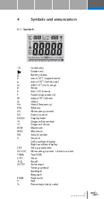
Страница 10: ...t M mega 106 ohm Ω Ohm Hz Hertz frequentie REL Relatief AC Wissel stroom spanning DC Gelijk stroom spanning HOLD Display hold ºF Graden Fahrenheit ºC Graden Celcius MAX Maximum MIN Minimum N0 Serie nummer S Tweede Linker display Rechter display SET Instellingen AC DC AC en DC TRMS True RMS STO Store Opslaan RCL Oproepen AUTO Auto Bereik Timing symbol Backlight Bargraph PEAK Peak hold V Volt Procen...

Страница 11: ... Druk op de RANGE toets het AUTO symbool verdwijnt 2 Druk op de RANGE toets om door de bereiken heen te stappen 3 Om terug te keren naar autobereik druk op de EXIT toets Het handmatige bereik is niet beschikbaar voor de temperatuurfuncties 4 3 MAX MIN 1 Druk op de MAX MIN toets om de MAX MIN mode te activeren Linksboven in het display wordt de maximale waarde weergegeven deze wordt ververst als er...

Страница 12: ...pscherm toont de initiële waarde het hoofdscherm toont de relatieve waarde 3 Met de EXIT toets wordt de relatieve mode weer verlaten Relatieve modus werkt niet in de 4 20mA functie 4 5 Achtergrondverlichting Druk op de toets om de achtergrondverlichting aan te zetten De verlichting schakelt automatisch uit 4 6 HOLD vasthouden De hold functie bevriest de actuele meetwaarde Met de HOLD kan deze func...

Страница 13: ...tussen de opnamen Selecteer met de en de gewenste periode Het bereik is 0 255 seconden 1 Als de intervaltijd tussen de opnamen op 0000 S staat druk dan opnieuw op STORE toets om waarden handmatig te bewaren 2 Druk nogmaals op de STORE toets om een waarde te bewaren 3 Als de intervaltijd tussen de 1 255 S is druk dan opnieuw op STORE toets om de opname auto matisch te starten 4 Opnamenummer wordt g...

Страница 14: ...e bediening van de RANGE toets selecteert de volgende parameters A bovenlimiet alarm B onderlimiet alarm C automatische uitschakeltijd D buzzer aan uit E tijd van de achtergrondverlichting 2 Gebruik toetsen om de parameter in te stellen 3 Via EXIT wordt dit menu verlaten 4 10 AC DC 1 Houdt in alle AC bereiken VAC mV AC 10 A AC mA AC en uA AC de EXIT toets 2 seconden in om de AC DC mode te activere...

Страница 15: ...teerd schakel over naar een hoger bereik 5 2 DC spanningmeting LET OP Meet geen DC spanningen als een motor in het circuit schakelt Hoge spannings pieken kunnen hierbij de meter beschadigen 1 Zet de functieschakelaar op de groene VDC positie 2 Sluit het zwarte meetsnoer met banaanstekker aan op de negatieve COM bus 3 Sluit het rode meetsnoer met banaanstekker aan op de positieve V bus 4 Verbind de...

Страница 16: ... spanning aanwezig is LET OP Meet geen AC spanningen als een motor in het circuit schakelt Hoge spanningspieken kunnen optreden die de meter kunnen beschadigen 1 Zet de functieschakelaar op de groene VAC Hz positie 2 Sluit het zwarte meetsnoer met banaanstekker aan op de negatieve COM bus 3 Sluit het rode meetsnoer met banaanstekker aan op de positieve V bus 4 Verbind de zwarte testprobe met de ne...

Страница 17: ...e spanning spieken kunnen optreden die de meter kunnen beschadigen 1 Zet de functieschakelaar op de groene mV positie 2 Druk op de MODE toets om DC of AC of in AC bereik drukt u op EXIT gedurende twee seconden en kies voor AC DC 3 Sluit het zwarte meetsnoer met banaanstekker aan op de negatieve COM bus 4 Sluit het rode meetsnoer met banaanstekker aan op de positieve V bus 5 Verbind de zwarte testp...

Страница 18: ...t 400 mA DC de functie schakelaar op de blauwe mA stand en sluit het rode meetsnoer met banaan plug aan op de uA mA bus 4 Voor stroommetingen tot 20 A DC stel de functie schakelaar op de blauwe 10 A Hz positie en sluit de rode testprobe met banaan plug aan op de 10 A aansluiting 5 Druk op de MODE toets om DC op het display te tonen 6 Haal de stroom van het te testen circuit af en open dan het circ...

Страница 19: ...de functie schakelaar op de blauwe mA stand en sluit u het rode testsnoer met banaan plug aan op de uA mA bus 4 Voor stroommetingen tot 20 A AC stel de functie schakelaar op de blauwe10 A Hz positie en sluit de rode testprobe met banaan plug aan op de 10 A aansluiting 5 Druk op de MODE toets om AC op het display te tonen 6 Haal de stroom van het te testen circuit af open dan het circuit op het pun...

Страница 20: ...sten apparaat uit en ontlaad alle condensatoren alvorens weer standmeting te starten Verwijder de batterijen en verwijder de voedingen 1 Zet de functieschakelaar op de groene Ω CAP positie 2 Sluit het zwarte meetsnoer met banaanstekker aan op de negatieve COM aansluiting 3 Sluit het rode meetsnoer met banaanstekker aan op de positieve Ω bus 4 Druk op de MODE toets om Ω op het display te tonen 5 Ve...

Страница 21: ...P positie 2 Sluit het zwarte meetsnoer met banaanstekker aan op de negatieve COM aansluiting 3 Sluit het rode meetsnoer met banaanstekker aan op de positieve Ω bus 4 Druk op de MODE toets om en Ω op het display te tonen 5 Verbind de testpunten met het te testen circuit of draad 6 Als de weerstand minder is dan ongeveer 35 Ω zal een geluidsignaal klinken Als het circuit open is zal OL in het displa...

Страница 22: ... te tonen in het display 5 Verbind de testprobes met de diode 6 Doorlaatspanning zal normaal 0 4 tot 0 7 V bedragen sperspanning zal als OL worden weergegeven kortgesloten diodes zullen ongeveer 0 V aangeven en onderbroken diodes zullen OL weergeven 5 10 Capaciteitsmeting WAARSCHUWING Om elektrische schokken te vermijden schakel het te testen apparaat uit en ontlaad alle condensatoren alvorens wee...

Страница 23: ... in het display 5 11 Temperatuurmeting 1 Zet de functieschakelaar op de groene temp positie 2 Sluit de temperatuurprobe aan op de ingangsbussen en controleer de polariteit 3 Druk op de MODE toets voor ºF of ºC te tonen 4 Raak met de kop van de temperatuurprobe het deel aan waar de temperatuur gemeten moet worden Blijf dit deel aanraken totdat de meting stabiliseert 30 sec 5 Lees de temperatuur af ...

Страница 24: ...uit het rode meetsnoer met banaanstekker aan de positieve Hz bus 4 Lees de frequentie af op het display 5 Druk op de MODE toets om te tonen 6 Lees de duty cycle af op het display 5 13 4 20 mA meting 1 Gebruik dezelfde instellingen als de DC mA meting 2 Zet de functieschakelaar op de blauwe 4 20 mA positie 3 De meter zal de circuit stromen als tonen waarbij 0 mA 25 4 mA 0 20 mA 100 en 24 mA 125 ...

Страница 25: ...tt com 5 14 RLO aard weerstandmeting met 200 mA 1 Zet de functieschakelaar op de rode RLO 200 mA positie 2 Sluit de testsnoeren aan op de bussen gemerkt met Riso Rlo 3 Verbind de meetsnoeren met de te testen weerstand ...

Страница 26: ...aarschuwing Als het te testen circuit een spanning heeft lager dan 30 V zal de isolatie test worden gestart Op het primaire display zal de isolatieweerstand MΩ worden getoond samen met een analoge aanduiding In de rechter bovenhoek wordt de testspanning weergegeven Het symbool verschijnt en een akoestisch signaal klinkt De test zal pas volledig zijn na 5 sec als de testspanning stabiel in beeld wo...

Страница 27: ... hoofd schakelaar omvatten 4 Als een verzwakking van de isolatie wordt geconsta teerd moeten de motor en andere onderdelen afzonderlijk worden gecontroleerd 5 Als de motor wordt uitgeschakeld bij de motor klemmen sluit een probe van de meter aan op de geaarde motorbehuizing en de andere op een van de draden van de motor 6 Om de borstelcontacten spoelen en armatuur te testen sluit een probe van de ...

Страница 28: ...ak ook het andere uiteinde los om fouten als gevolg van lekstromen van apparatuur te voor komen 3 Controleer elke geleider met massa en afscherming door verbinden met een van de probes van de meter op de aarde en afscherming en de andere probe op elk van de geleiders afzonderlijk ...

Страница 29: ... PI standaard PI waarde Status 2 4 meestal 3 Beschouwd als goede isolatie oudere types 1 1 5 Niet aanvaardbaar oudere types 1 zeer hoge isolatieweer stand Modern type goed isolatiesysteem 1 0 of minder Fout Voorbeeld Als de meting van B klasse isolatiemateriaal 100 M in 1 minuut is 110 MΩ in 10 minuten is de polarisa tie index 1 1 110 mΩ 100 MΩ 1 1 Als het isolatiemateriaal te veel water bevat of ...

Страница 30: ... Max 80 bij 31 ºC 87 ºF verminderend tot 50 bij 40 ºC 104 ºF Opslag luchtvochtigheid 80 Opslaggeheugen 2000 Gewicht 631 g Afmetingen 220 x 96 5 x 60 5 mm Diode test Test stroom 0 9 mA maximum open circuit spanning 2 8 VDC nominaal Doorgangscontrole Geluidssignaal zal klinken indien de weerstand 35 Ω test stroom 0 35 mA Peak hold Detecteerd pieken 1 ms Ingangs impedantie 10 MΩ VDC 9 MΩ VAC AC metin...

Страница 31: ... 1 μA 50 mA 0 001 mA 500 mA 0 01 mA 10 A 0 001 A 20 A 30 sec max met lagere nauwkeurigheid AC DC stroom 500 μA 0 1 μA 1 5 7 d 5000 μA 1 μA 50 mA 0 01 mA 500 mA 0 1 mA 50 A 0 01 A 20 A 30 sec max met lagere nauwkeurigheid Alle AC spanningbereieken worden gespecificeerd van 5 to 100 van het bereik Max hoogte 2000 meter 7000 feet Drop test 2 meters 6 5 feet Behuizing Dubbel gespoten waterproof Catego...

Страница 32: ...0 001 μF 500 μF 0 01 μF 5000 μF 0 1 μF 5 0 10 d 50 mF 0 001 mF Frequentie niet sinus 50 Hz 0 001 Hz 0 1 1 d 500 Hz 0 01 Hz 5 kHz 0 0001 kHz 50 kHz 0 001 kHz 500 kHz 0 01 kHz 5 MHz 0 0001 MHz 50 MHz 0 001 MHz 100 MHz 0 01 MHz Niet gespecificeerd Gevoeligheid 0 8V rms min 20 80 duty cycle en 100 kHz 5V rms min 20 80 duty cycle en 100 kHz Frequentie sinus 50 00Hz 10KHz 0 1Hz 0 001kHz 0 5 Gevoeligheid...

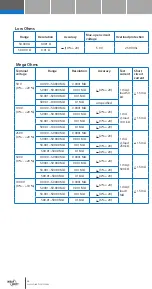
Страница 33: ...Ω 0 1 MΩ 4 20 250 V 0 20 0 0100 5 0000 MΩ 0 0001 MΩ 2 20 1 mA load 250 kΩ 1 5 mA 5 0001 50 000 MΩ 0 001 MΩ 50 001 500 00 MΩ 0 01 MΩ 3 20 500 01 5000 MΩ 0 1 MΩ 4 20 500 V 0 20 0 0100 5 0000 MΩ 0 0001 MΩ 2 20 1 mA 500 kΩ 1 5 mA 5 0001 50 000 MΩ 0 001 MΩ 50 001 500 00 MΩ 0 01 MΩ 3 20 500 01 5000 MΩ 0 1 MΩ 4 20 1000 V 0 10 0 0100 5 0000 MΩ 0 0001 MΩ 2 20 1 mA load 1 MΩ 1 5 mA 5 0001 50 000 MΩ 0 001 MΩ...

Страница 34: ...wordt Gebruik en berg de multimeter op bij normale temperaturen Extreme temperaturen kunnen de levensduur van de elektronische onderdelen verkorten en kunnen kunststof onderdelen vervormen of smelten Gebruik de multimeter voorzichtig en zorgvuldig Vallen kan de elektronische onderdelen of de behuizing beschadigen Houd de multimeter schoon Reinig de behuizing met een vochtige doek GEEN chemicaliën ...

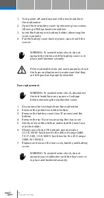
Страница 35: ...ijn en dat ze goed geplaatst zijn Zekering vervangen WAARSCHUWING Om een elektrische schok te vermijden ontkoppel de meetsnoeren van elke spanningsbron voordat u de deksel opent 1 Schakel de multimeter uit en ontkoppel de meets noeren van de meter 2 Open de batterijdeksel aan de achterzijde door de twee schroeven B 3 Verwijder de 6 A schroeven die de achterzijde vasthouden 4 Verwijder voorzichtig ...

Страница 36: ...3 AC voltage measurement 49 5 4 mV voltage measurement 50 5 5 DC current measurement 51 5 6 AC current measurement 52 5 7 Resistance measurement 53 5 8 Continuity check 54 5 9 Diodetest 55 5 10 Capacitance measurement 55 5 11 Temperature measurement 56 5 12 Frequency 57 5 13 4 20 mA measurement 57 5 14 RLO resistancemeasurement with 200 mA 58 5 15 Insulation resistance measurement 59 5 16 Motors 6...

Страница 37: ...meter This WARNING symbol indicates a potentially hazardous situation which if not avoided could result in death or serious injury This CAUTION symbol indicates a potentially hazardous situation which if not avoided may result damage to the product This symbol advises the user that the terminal s so marked must not be connected to a circuit point at which the voltage with respect to earth ground e...

Страница 38: ...e as marked on the multimeter between terminals or between any terminal and earth ground Only replace the blown fuse with the proper rating as specified in this manual Use caution with voltages above 30 VAC RMS 42 VAC peak or 60 VDC These voltages pose a shock hazard To avoid false readings that can lead to electric shock and injury replace battery as soon as low battery indicator Disconnect circu...

Страница 39: ...harge filter capacitors in power supplies and disconnect the power when making resistance or diode tests Always turn off the power and disconnect the test leads before opening the covers to replace the fuse or batteries Never operate the meter unless the back cover and the battery and fuse covers are in place and fastened securely If the equipment is used in a manner not specified by the manufactu...

Страница 40: ...Y II is energy consuming equipment to be supplied from the fixed installation Examples include household office and laboratory appliances Overvoltage category III Equipment of OVERVOLTAGE CATEGORY III is equipment in fixed installations Examples include switches in the fixed installation and some equipment for industrial use with permanent connection to the fixed installation Overvoltage category ...

Страница 41: ...ency Resistance Duty cycle Temperature C F 4 20 mA Insulation Features True RMS Insulation resisancemeasurements100 250 500 1000 V Automatic AC DC voltagedetection Current measurement 20 A AC DC Capacity Continuity diodetest IP 67 waterproof Peak hold Min max hold Automatic power off Memory Backlight Resolution 40 000d Overvoltage category CAT III 1000 V CAT IV 600 V Inspection Once your new digit...

Страница 42: ... Min max button 3 Store button RECALL 4 Range button SETUP 5 Insulationtest button 6 Mode button 7 Function switch 8 mA µA and 10A input jacks 9 Rel button 10 Hold button PEAKHOLD 11 Exit button AC DC 12 Backlght 13 Positive input jack 14 Com input jack ...

Страница 43: ...s Ω Ohms Hz Hertz frequency REL Relative AC Alternating current DC Direct current HOLD Display hold ºF Degrees Fahrenheit ºC Degrees Celcius MAX Maximum MIN Minimum N0 Serial number S Second Left auxiliary display Right auxiliary display SET Set up parameter AC DC Alternating current direct current TRMS True RMS STO Store RCL Recall AUTO Autorange Timing symbol Backlight Bargraph PEAK Peak hold V ...

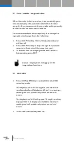
Страница 44: ... RANGE key to step through the available ranges until you select the range you want 3 To exit the Manual Ranging mode and return to Autoranging press EXIT Manual ranging does not apply for the temperature functions 4 3 MAX MIN 1 Press the MAX MIN key to activate the MAX MIN recording mode The display icon MAX will appear The meter left auxiliary displaywill display and hold the maximum reading and...

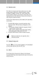
Страница 45: ...n to store the reading in the display and the REL indicator will appear on the display 2 Left auxiliary display display the margin of initial value and the current value Right auxiliary display display the initial reading Main display the reading after REL TEST 3 Press the EXIT button to exit the relative mode Relative mode does not operate in the 4 20mA function 4 5 Display background Press the k...

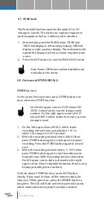
Страница 46: ...rage serial number On the right upper corner of LCD shows XXXX S which states how many current storage is used 1 On the left upper shows 0000 S which states recording interval time using button to select S the range is 0 255 seconds 2 When the recording interval time is 0000 S then press STORE button again to change into manual recording Press the STORE button again to record once 3 When the recor...

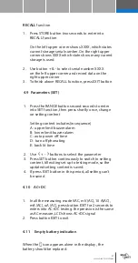
Страница 47: ...ange on setting content Setting content includes in sequence A upper limit buzzer alarm B lower limit buzzer alarm C auto power off time D turn off phonating E back lit time 2 Use buttons to select the parameter 3 Press SET button continuously to switch to setting content till exiting set up to testing mode so the updated setting content is saved 4 If press EXIT button in this period all setting c...

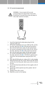
Страница 48: ...d change to a higher range 5 2 DC voltage measurement CAUTION Do not measure DC voltages if a motor on the circuit is being switched ON or OFF Large voltage surges may occur that can damage the meter 1 Set the function switch to the green VDC position 2 Insert the black test lead banana plug into the negative COM jack 3 Insert the red test lead banana plug into the positive V jack 4 Touch the blac...

Страница 49: ...switched ON or OFF Large voltage surges may occur that can damage the meter 1 Set the functionswitch to the green VAC Hz position 2 Insert the black test lead banana plug into the negative COM jack 3 Insert red test lead banana plug into the positive V jack 4 Touch the black test probe tip to the neutral side of the circuit 5 Touch the red test probe tip to the hot side of the circuit 6 Read the v...

Страница 50: ...he green mV position 2 Press the MODE button to indicate DC or AC or in AC range press EXIT for two seconds and chose AC DC 3 Insert the black test lead banana plug into the negative COM jack 4 Insert the red test lead banana plug into the positive V jack 5 Touch the black test probe tip to the negative side of the circuit 6 Touch the red test probe tip to the positive side of the circuit 7 Read t...

Страница 51: ... to 400 mA DC set the function switch to the blue mA position and insert the red test lead banana plug into the µA mA jack 4 For current measurements up to 20 A DC set the function switch to the blue 10 A Hz position and insert the red test lead banana plug into the 10 A jack 5 Press the MODE button to indicate DC on the display 6 Remove power from the circuit under test then open up the circuit a...

Страница 52: ...tion and insert the red test lead banana plug into the µA mA jack 4 For current measurements up to 20 A AC set the function switch to the blue 10 A Hz position and insert the red test lead banana plug into the 10 A jack 5 Press the MODE button to indicate AC on the display 6 Remove power from the circuit under test then open up the circuit at the point where you wish to measure current 7 Touch the...

Страница 53: ...all capacitors before taking any resistance measurements Remove the batteries and unplug the line cords 1 Set the function switch to the green Ω CAP position 2 Insert the black test lead banana plug into the negative COM jack 3 Insert the red test lead banana plug into the positive Ω jack 4 Press the MODE button to indicate Ω on the display 5 Touch the test probe tips across the circuit or part un...

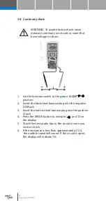
Страница 54: ...position 2 Insert the black lead banana plug into the negative COM jack 3 Insert the red test lead banana plug into the positive Ω jack 4 Press the MODE button to indicate and Ω on the display 5 Touch the test probe tips to the circuit or wire you wish to check 6 If the resistance is less than approximately 35 Ω the audible signal will sound If the circuit is open the display will indicate OL ...

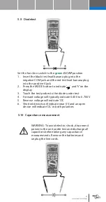
Страница 55: ... display 3 Touch the test probes to the diode under test 4 Forward voltage will typically indicate 0 400 to 0 700 V 5 Reverse voltage will indicate OL 6 Shorted devices will indicate near 0 V and an open device will indicate OL in both polarities 5 10 Capacitance measurement WARNING To avoid electric shock disconnect power to the unit under test and discharge all capacitors before taking any capac...

Страница 56: ...rment 1 Set the function switch to the green Temp position 2 Insert the temperature Probe into the input jacks make sure to observe the correct polarity 3 Press the MODE button to indicate ºF or ºC 4 Touch the temperature probe to the part which temperature you wish to measure keep the probe touching the part under test until the reading stabilizes about 30 seconds 5 Read the temperature in in het...

Страница 57: ... the positive Hz jack 3 Touch the test probe tips to the circuit under test 4 Read the frequency on the display 5 Press the MODE button to indicate 6 Read the duty cycle in the display 5 13 4 20 mA measurement 1 Set up and connect as described for DC mA measurements 2 Set the rotary function switch to the 4 20 mA position 3 The meter will display loop current as a with 0 mA 25 4 mA 0 20 mA 100 and...

Страница 58: ...om 5 14 RLO Earth resistance measurement with 200 mA 1 Set the function switch to the red RLO 200 mA position 2 Insert the testleads to the Riso Rlo jacks 3 Connect the testprobes with both end of the resistance under test ...

Страница 59: ...l testing process and bring the high voltage on the primary display The insulation resistance in MΩ is indicated in phase with analog bar on the top right corner display the tested insulation voltage in V DC is indicated the symbol flashes and the buzzer warns frequently 4 Being free from the TEST button or pushing the TEST button in the LOCK status can exit from the LOCK status and shutoff the hi...

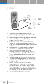
Страница 60: ...uld be checked individually 5 If the motor is disconnected at the motor terminals connect one megohmmeter lead to the grounded motor housing and the other lead to one of the motor leads Disconnect the motor from the line 6 To test the brush rigging field coils and armature connect one megohmmeter lead to the grounded motor housing and the other lead to the brush on the commutator 7 If the resistan...

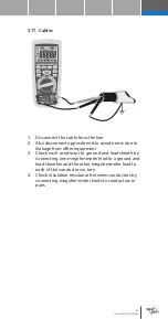
Страница 61: ... due to leakage from other equipment 3 Check each conductor to ground and lead sheath by connecting one megohmmeter lead to a ground and lead sheather and the other megohmmeter lead to each of the conductors in turn 4 Check insulation resistance between conductors by connecting megohm meter leads to conductors in pairs ...

Страница 62: ...erial status 2 4 typically 3 Considered as good insulation older types 1 1 5 Not acceptable older types 1 very high insulation re sistance Modern type of good insulation system 1 0 or less Fail Example If the reading of B class insulation material is 100 M in 1 minute 110 MΩ in 10 minutes polarization index is 1 1 110 mΩ 100 MΩ 1 1 As the insulating material contains too much water or seriously po...

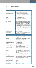
Страница 63: ... 31 ºC 87 ºF decreasing linearly to 50 at 40 ºC 104 ºF Storage humidity 80 Store capacitance 2000 Weight 631 g Dimensions 220 x 96 5 x 60 5 mm Diode test Test current of 0 9 mA maximum open circuit voltage 2 8 VDC typical Continuity check Audible signal will sound if the resis tance is less than 35 Ω approx test current 0 35 mA Peak Captures peaks 1 ms Input impedance 10 MΩ VDC 9 MΩ VAC AC respons...

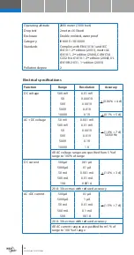
Страница 64: ...0 01 mV 0 06 4 d 5 V 0 0001 V 50 V 0 001 V 500 V 0 01 V 1000 V 0 1 V 0 1 5 d AC DC voltage 50 mV 0 001 mV 1 0 7 d 50 60 Hz 500 mV 0 01 mV 5 V 0 001 V 50 V 0 01 V 500 V 0 1 V 1000 V 1 V All AC voltage ranges are specified from 5 of range to 100 of range DC current 500 μA 0 01 μA 1 0 3 d 5000 μA 0 1 μA 50 mA 0 001 mA 500 mA 0 01 mA 10 A 0 001 A 20 A 30 sec max with reduced accuracy AC DC current 500...

Страница 65: ...5 10 d 50 μF 0 001 μF 500 μF 0 01 μF 5000 μF 0 1 μF 5 0 10 d 50 mF 0 001 mF Frequency electronic 50 Hz 0 001 Hz 0 1 1 d 500 Hz 0 01 Hz 5 kHz 0 0001 kHz 50 kHz 0 001 kHz 500 kHz 0 01 kHz 5 MHz 0 0001 MHz 50 MHz 0 001 MHz 100 MHz 0 01 MHz Not specified Sensitivity 0 8Vrmsmin 20 80 dutycycle and 100kHz 5V rms min 20 80 duty cycle and 100 kHz Frequency elec trical 50 00Hz 10KHz 0 1Hz 0 001kHz 0 5 Sens...

Страница 66: ...00 0 MΩ 0 1 MΩ 4 20 250 V 0 20 0 0100 5 0000 MΩ 0 0001 MΩ 2 20 1 mA load 250 kΩ 1 5 mA 5 0001 50 000 MΩ 0 001 MΩ 50 001 500 00 MΩ 0 01 MΩ 3 20 500 01 5000 MΩ 0 1 MΩ 4 20 500 V 0 20 0 0100 5 0000 MΩ 0 0001 MΩ 2 20 1 mA 500 kΩ 1 5 mA 5 0001 50 000 MΩ 0 001 MΩ 50 001 500 00 MΩ 0 01 MΩ 3 20 500 01 5000 MΩ 0 1 MΩ 4 20 1000 V 0 10 0 0100 5 0000 MΩ 0 0001 MΩ 2 20 1 mA load 1 MΩ 1 5 mA 5 0001 50 000 MΩ 0 ...

Страница 67: ...peratures Temperature extremes can shorten the life of the electronic parts and distort or melt plastic parts Handle the multimeter gently and carefully Dropping it can damage the electronic parts or the case Keep the multimeter clean Wipe the case occasionally with a damp cloth DO NOT use chemicals cleaning solvents or detergents Use only fresh batteries of the recommended size and type Remove ol...

Страница 68: ...serted Fuse replacement WARNING To avoid electric shock disconnect the test leads from any source of voltage before removing the multimeter cover 1 Disconnect the test leads from the multimeter 2 Remove the protective rubber holster 3 Remove the battery cover two B screws and the battery 4 Remove the six A screws securing the rear cover 5 Gently remove the old fuse and install the new fuse into th...

Отзывы: