41
5.
Achieving optimum results
and avoiding incorrect usage
It is recommended that:
■
The borer
should be fitted and tensioned with the key in such a way that the borer is positioned
precisely between the three clamping jaws of the crown gear, quick clamping or collet chuck
■
Clamp the milling machine with shaft
using the collet chuck and the appropriate collets
■
Clamp the milling machine with bored hole
and longitudinal groove using the plugged milling
machine spike
When boring, attention is to be paid that:
■
The appropriate revolutions are set according to the diameter of the borer
■
The pressure is gentle enough that the borer is able to cut without straining
■
In the event of too much pressure, the result is early borer wear or even borer breakage or
jamming in the bored hole.
In the event of jamming, immediately bring the main drive motor
to a standstill by pressing the emergency off switch
■
When using hard materials, for example, steel, ordinary boring oil must be used
■
The borer is always to be removed from the work piece with the spindle rotating
■
When using non-metal materials, for example, wood, tearing on breakthrough can be prevents by
clamping a piece of waste wood under the work piece to be processed
■
For wood work pieces with a veneer or plastic coating, always work from the side with the veneer
■
With very thin sheets, also clamp using a piece of waste wood
When milling, attention is to be paid that:
■
The appropriate cutting speed is selected (see the section on revolution setting)
For materials with normal firmness values, e.g. steel 18-22m/min
For materials with higher firmness values 10-14m/min
■
The pressure is to be selected so that the cutting speed remains constant
■
For hard materials, use ordinary boring oil
When clamping the work pieces, attention should be paid that:
■
The appropriate clamping screws are used for the T grooves of the milling machine table or use a
machine vice
■
The milling machine table of the cross slide support is to be cleaned of dirt residue and shavings
in order to ensure perfectly even clamping
Содержание CC-F1200 high speed
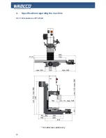
Страница 27: ...27 4 Specifications regarding the machine 4 3 2 Dimensions of F1200 C for ball screw spindle only...
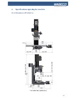
Страница 28: ...28 4 Specifications regarding the machine 4 3 3 Dimensions of F1200 C hs for ball screw spindle only...
Страница 30: ...30 4 Specifications regarding the machine 4 3 5 Dimensions of F1210 C for ball screw spindle only...
Страница 31: ...31 4 Specifications regarding the machine 4 3 6 Dimensions of F1210 C hs for ball screw spindle only...
Страница 34: ...34 4 Specifications regarding the machine 4 4 2 Dimensions of CC F1200 for ball screw spindle only...
Страница 35: ...35 4 Specifications regarding the machine 4 4 3 Dimensions of CC F1200 hs for ball screw spindle only...
Страница 37: ...37 4 Specifications regarding the machine 4 4 5 Dimensions of CC F1210 for ball screw spindle only...
Страница 38: ...38 4 Specifications regarding the machine 4 4 6 Dimensions of CC F1210 hs for ball screw spindle only...
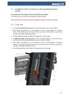
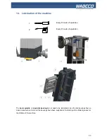
Страница 42: ...42 6 Fitting and removing the tools 1 2 3 4 5...
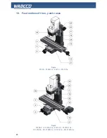
Страница 66: ...66 17 Drawings and legends 17 2 Electronic hood with 1 4 kW motor 17 2 1 F1200 F1210 F1200 C F1210 C...
Страница 68: ...68 17 Drawings and legends 17 2 Electronic hood with 1 4 kW motor 17 2 2 CC F1200 CC F1210...
Страница 70: ...70 17 Drawings and legends 17 3 Milling head with 1 4 kW motor...
Страница 72: ...72 40 1 51004008 0002 Mounting pin 17 Drawings and legends 17 4 Milling head with 2 0 kW motor...
Страница 74: ...74 17 Drawings and legends 17 4 Milling head with 2 0 kW motor...
Страница 76: ...76 17 Drawings and legends 17 5 Z stand with vertical skid with trapezoidal threaded spindle...
Страница 82: ...82 17 7 Lateral drive for z axis with trapezoidal threaded spindle 17 Drawings and legends...
Страница 84: ...84 17 8 Cross slide support with trapezoidal threaded spindle 17 Drawings and legends...
Страница 94: ...94 17 Drawings and legends 17 11 Z stand with vertical skid with ball screw spindle...
Страница 96: ...96 17 Drawings and legends 17 12 Spindle z axis with ball screw spindle 17 12 1 F1200 F1200 hs F1210 F1210 hs...
Страница 100: ...100 17 Drawings and legends 17 13 Lateral drive for z axis with ball screw spindle...
Страница 102: ...102 17 Drawings and legends 17 14 Cross slide support with ball screw spindle...
Страница 104: ...104 17 Drawings and legends 17 15 Spindle x axis with ball screw spindle 17 15 1 F1200 F1200 hs F1210 F1210 hs...
Страница 108: ...108 17 Drawings and legends 17 16 Spindle y axis with ball screw spindle 17 16 1 F1200 F1200 hs F1210 F1210 hs...
Страница 114: ...114 17 Drawings and legends 17 20 Operating console for 1 4 kW motor...
Страница 116: ...116 17 Drawings and legends 17 20 Operating console for 1 4 kW motor...
Страница 118: ...118 17 Drawings and legends 17 21 Operating console for 2 0 kW motor...
Страница 120: ...120 17 Drawings and legends 17 21 Operating console for 2 0 kW motor...
Страница 122: ...122 17 Drawings and legends 17 22 Bracket arm for operating console...
Страница 124: ...124 17 Drawings and legends 17 23 Industrial monitor and folio keyboard...


