background image


29 


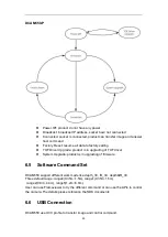
DCAM550-P 


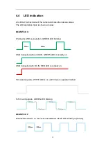
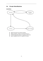
  Power Off: product do not have any power   

  Broadcast: broadcast IP address, socket have not connected 

  Connected: socket is connected, product can transfer image and answer 

host command 

  Factory Reset: resume all data to factory setting 

  TOF Driver Upgrade: product is in upgrading of TOF driver 

  System Upgrade: product is in upgrading of firmware 

6.5 

Software Command Set 

DCAM550 support different work mode like depth_30, IR_30, depth&IR_30.   

Three default range: range0(0.35m~1.5m), range1(0.35m~1.5m), 

  range2(0.8m~4.4m), range5(1.2m~6.0m). 

User can use Frameviewer to try the different command or can use the APIs to control 

the camera. The details please reference the SDK documents. 

6.6 

USB Connection 

DCAM550 use UVC profile to transfer image and control command.  


Содержание DCAM550

Страница 1: ...1 Vzense DCAM550 ToF Camera User Manual DCAM550U DCAM550P ...

Страница 2: ... 1 Hardware Requirements 12 3 6 2 Software Requirements 12 3 6 3 Environmental Requirements 12 3 6 4 Coordinate of the Camera System 13 4 Interface with Host 14 4 1 6pin Connector 15 4 2 Type A USB2 0 Connector for DCAM550 U 16 4 3 RJ45 Ethernet Connector for DCAM550 P 16 4 4 LED indication 17 4 5 IP Reset Button for DCAM550 P 18 5 Principle of Time of Flight 19 5 1 Vzense ToF Principle 19 5 2 Noi...

Страница 3: ...Wide Dynamic Range 31 7 4 Data Filtering 32 7 5 IR Image 32 8 Camera Operation on Frameviewer 34 8 1 Main screen 34 8 1 1 Image area 35 8 1 2 Command and information area 35 8 2 Connect devices 36 8 3 2D view 36 8 3 1 Depth Image 36 8 3 2 IR Image 37 8 4 3D image store 37 8 5 Camera Control 38 8 5 1 Mode switch 38 8 5 2 Range change 38 8 6 WDR 39 9 DCAM550 Accessories and Package 42 10 Customizati...

Страница 4: ...umber can t be read from the camera s registers Do not open the camera housing Do not open the housing Touching any internal components may damage the camera Prevent any objects or substances from entering the camera housing Otherwise the camera may fail or damaged Avoid electromagnetic fields Do not use the camera near strong electromagnetic fields Prevent from electrostatic charging Transport in...

Страница 5: ... DC power With USB power the working distance will be limited by the USB host power ability Normally the USB2 0 host can supply up to 5V 500mA current USB3 0 host can supply up to 5V 900mA current We strongly suggest to use external DC power if you require far distance which more than 4 meters The DC power can accept 11V 26V power source For higher than 26V or lower than 11V the device shall not w...

Страница 6: ...ost Incorrect plugging in and unplugging of the camera s power cable can damage the camera To avoid switch on surges damaging the camera please plug in the power cable into the camera s 6 pin connector firstly before getting power supply Don t try to change the position of the lens may cause damage to the camera Do store the camera carefully when not in use in original package the best 2 4 Tempera...

Страница 7: ...ower Consumption Average Max 5W Ref Illumination 940nm 2 x 2W Vcsel Dimension L W H DCAM550 U 65mm 65mm 52 7mm DCAM550 P 65mm 65mm 52 7mm Weight DCAM550 U 265g DCAM550 P 279g Power Supply DCAM550 U USB or DC Power DCAM550 P PoE or DC Power Interface DCAM550 U USB OTG and RS485 DCAM550 P Ethernet and RS485 Digital I O Exposure Control Synchronization etc 1in 1out Passive Sync Signal Enclosure Ratin...

Страница 8: ... 1200mm 30fps 238 334 mA Range 1 500mm 2800mm 30fps 374 545 mA Range 2 800mm 4400mm 30fps 438 661 mA Range 5 1200mm 6000mm 15fps 478 1196 mA Note 12V input voltage 3 2 3 Absolute Maximum Ratings This is a stress rating only and functional operation of the devices at those or any other conditions above those indicated in the operation listings of this specification is not promised Exposure to maxim...

Страница 9: ...anical Specifications This drawing contains information about the dimensions and user mounting location of the ToF Camera Front View Back View Bottom View Top View Left View Right View Fig 3 1 ToF Camera Dimensions Unit mm ...

Страница 10: ...anical Specifications This drawing contains information about the dimensions and user mounting location of the ToF Camera Front View Back View Bottom View Top View Left View Right View Fig 3 2 ToF Camera Dimensions Unit mm ...

Страница 11: ...hoices according to the lens FOV and wavelength The laser FOV must match to the lens FOV and the wider FOV products need stronger power therefore higher power consumption Even with higher power supplied the laser power per angle of the wider FOV product may be reduced so normally the maximum distance of wider FOV products is shorter than narrower FOV products As for the wavelength we have 850nm an...

Страница 12: ...cluded in package 3 6 2 Software Requirements Operating system 32 bit Windows 7 10 64 bit Windows 7 10 recommended Linux x86 x64 Android 5 0 or above Vzense ToF Driver The Vzense ToF Driver software is available for Windows Linux and Android operating systems and includes the following SDK code Sample code Software user manual 3 6 3 Environmental Requirements Temperature and Humidity Housing tempe...

Страница 13: ...era coordinate system CCS one is world coordinate system WCS CCS CCS describe the two dimensional data the origin of coordinates is the optic center WCS WCS describe the three dimensional information The CCS data can switch to the WCS data using the camera internal parameters Fig 3 3 Origin of the Coordinate System Meshlab and CloudCompare tools are recommended to analyze the point cloud data save...

Страница 14: ...ore information about pin assignments and connector types see the following sections Fig 4 1 Camera Connectors DCAM550 P ToF Camera is equipped with RJ45 LED 6pin connector IP reset button at the back of its housing as shown in below figure For more information about pin assignments and connector types see the following sections Fig 4 2 Camera Connectors ...

Страница 15: ...rigger input 3 3V 20V 4 Exposure_timing OUTPUT Control signal output 1 5 GND GND System ground 6 Ext_OUT OUTPUT Control signal output from processor Hardware Trigger Function Hardware trigger mode is available only when the camera works at slave mode in slave mode the camera will wait for the hardware trigger signal on Ext_Trigger The EXT_Trigger signal is to driver the MOSFET External input trigg...

Страница 16: ...which means a low level signal indicates the exposure period Please refer to below figure Exposure Exposure Exposure_timing Pin 4 2 Type A USB2 0 Connector for DCAM550 U DCAM550 U has the Type A 2 0 interface for data transmission and power supply By default the DCAM550 U works as USB slave at all time The USB port can work as USB host by customization from Vzense team if you really need the USB O...

Страница 17: ...iting for USB enumeration GREEN LED blinking USB Connected without DC IN GREEN LED constantly on USB Connected with DC IN RED LED constantly on Firmware Upgrade WHITE LED is on until firmware upgrade finished ToF driver Upgrade GREEN LED blinking DCAM550 P Ethernet Broadcast no connection established BLUE LED blinking repeatedly 200ms 2800m s ...

Страница 18: ...ct reset itself Firmware Upgrade WHITE LED is on until firmware upgrade finished ToF driver Upgrade GREEN LED blinking repeatedly 4 5 IP Reset Button for DCAM550 P A hidden button hole is for IP reset a pin shall be used to press the button While the camera is powered on long pressing the button for 10 seconds until the LED is off Then the IP is reset as 192 168 1 101 ...

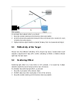
Страница 19: ...ra any additional light e g artificial light sources or sunlight may influence the measurement results A strong ambient light may affect the accuracy and precision of the depth data the Zense DCAM 710 is suggested to in user below 50K LUX ambient light 5 2 Multipath Propagation Based on the principle of ToF Multipath effect may happen when the light reflected more one once Any light that has been ...

Страница 20: ...ifferent reflectivity of the target may cause measurement result deviation objects which have 20 to 80 reflectivity to 850nm or 940nm infrared light have the best result 5 4 Scattering Effect Scattering light effect is a noise factor to ToF products it is caused by multiple reflection inside the lens of camera or the cover of camera To eliminate the scattering light effect you should 1 Keep the co...

Страница 21: ... 0 host can supply power to camera for the application of long distance which needs more power consumption the multiple functional cable VZENSE MFP 6P B shall be in use The steps are as below 1 Mount the camera in an appropriate fixture e g a camera bracket 2 Plug the male end of the USB2 0 type A cable VZENSE USB TYPEA CABLE into the type A female jack at the back of the camera and plug the other...

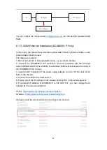
Страница 22: ... host processor with the Ethernet cable VZENSE LAN CAT5e CABLE the standard RJ45 socket locates at the back of the DCAM550 P ToF camera 3 Insert the DC connector of the power supply adaptor into the 12V DC Jack at the back of the camera 4 Connect the adaptor to power source 5 Please do set the IP address of the camera and host PC in the same segment 6 The default IP address of DCAM550 P is 192 168...

Страница 23: ... an installation Time and cost savings by reducing the time and expense of having electrical power cabling installed Network cables do not require a qualified electrician to fit them and can be located anywhere Flexibility without being tethered to an electrical outlet devices such as IP cameras and wireless access points can be located wherever they are needed most and repositioned easily if requ...

Страница 24: ... cost unmanaged edge switcheswith a few ports up to complex multi port rack mounted units with sophisticated management A midspan or POE injector is used to add POE capability to regular non POE network links Midspans can be used to upgrade existing LAN installations to POE and provide a versatile solution where fewer POE ports are required Upgrading each network connection to POE is as simple as ...

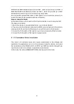
Страница 25: ... g a camera bracket 2 Plug one end of the Ethernet cable into the RK45 socket at the back of the camera and plug the RJ45 end into the Ethernet port of your PoE switch or PoE injector 3 Connect the PoE switch or PoE injector to your host processor by Ethernet cable 4 Connect the PoE switch or PoE injector to power source 6 1 5 Standalone Mode Installation This mode is for advanced users who requir...

Страница 26: ...sion based on the product and system Windows SDK Linux SDK have different project repository 6 2 2 Graphic Tool on windows Vense uTool is a graphic tool on windows for the all Vzense ToF products Download or clone uTool evaluation tool from our GitHub Gitee China https gitee com Vzense UTool Oversea https github com Vzense UTool Please do read the Vzense_UTool_User_guide pdf before using ...

Страница 27: ...d version app in Tools folder the source code is in Samples folder See the document for the details 6 3 Firmware Upgrade Download the VzenseUpgradeTool from below link China https gitee com Vzense VzenseUpgradeTool Oversea https github com Vzense VzenseUpgradeTool Please read the Vzense_UpgradeTool_User_Guide pdf before upgrading firmware ...

Страница 28: ...tate Machine DCAM550 U Power Off product do not have any power Working product is ready for connect and frame out TOF Driver Upgrade product is in upgrade of TOF driver System Upgrade product is in upgrade of firmware ...

Страница 29: ...rading of TOF driver System Upgrade product is in upgrading of firmware 6 5 Software Command Set DCAM550 support different work mode like depth_30 IR_30 depth IR_30 Three default range range0 0 35m 1 5m range1 0 35m 1 5m range2 0 8m 4 4m range5 1 2m 6 0m User can use Frameviewer to try the different command or can use the APIs to control the camera The details please reference the SDK documents 6 ...

Страница 30: ...The slave trigger mode can be used to implement multiple products synchronization one works as master the other works as slave Please refer to Multiple_ToF_Products_Synchronization_Application_Note pdf for more information 7 2 Range Customization By default there are 4 different range modes calibrated for DCAM550 please see below table for more information Range number Distance range Range 0 0 35m...

Страница 31: ...ar limitation is 0 4m then the furthest distance in this mode can reach about 2m Wide dynamic range means that the camera can work at more than one range modes alternately then the camera itself will combine the frames of all ranges into one depth frame therefore can expand the range limitation from furthest distance to nearest distance However the frame rate will be reduced 0 0 005 0 01 0 015 0 0...

Страница 32: ...ering algorithm includes Median filtering Gaussian filtering Bilateral filtering Timing filtering Flying pixel removing 7 5 IR Image Besides the depth image Vzense DCAM550 camera can also output a VGA resolution IR image And the IR image is exactly timing synchronized with the depth image Pixel to pixel mapping is also exactly aligned 0 0 5 1 1 5 2 2 5 3 3 5 4 DISTANCE ERROR DISTANCE RANGE UNIT MM...

Страница 33: ...33 ...

Страница 34: ...n 30fps IR 30 IR image in 30fps Depth IR 30 both depth and ir in 30fps WDR see the detail in below Range Change Range 0 7 different depth detect range Exposure parameter modify Pulse count laser pulse parameter Gamma gain IR image gamma gain Filters switch different image filters IR_BG the background light swtich 8 1 Main screen Frameviewer have some areas for different function for example image ...

Страница 35: ...area is the area of showing depth image IR image 8 1 2 Command and information area Frameviewer use CMD shell for camera control and information output Like the image below switch mode change detect range save 3D image and so on ...

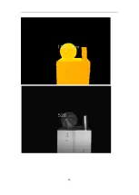
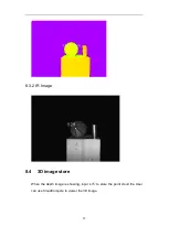
Страница 36: ...ut the base information on the window 8 3 2D view The display area can show different type image 8 3 1 Depth Image Depth image is covert to a rainbow image for real distance showing Depth Image with color map COLORMAP_RAIN BOW Color_Map_Mi n 255 0 Color_Map_Ma x 8bit 16bit ...

Страница 37: ...37 8 3 2 IR Image 8 4 3D image store When the depth image is showing input s S to store the point cloud file User can use CloudCompare to viewer the 3D image ...

Страница 38: ...Depth IR_30 depth and IR image all in 30 fps 8 5 2 Range change By default DCAM550 product has 4 different range modes calibrated please see below table for more information Range number Distance range Range 0 0 35m 1 5m Range 1 0 5m 2 8m Range 2 0 8m 4 4m Range 5 1 2m 6 0m Please do NOT use uncalibrated modes the measurement data will not be guaranteed ...

Страница 39: ...e multi range image to extend the detect range For example if you want to get the distance from 0 35m to 4 4m only one range mode can t cover the whole distance Use range 0 and 2 WDR can match this requirement Configure the WDR mode If you have some particular requirement and want to use WDR mode you can contract with Vzense FAE first Change mode to WDR mode ...

Страница 40: ...40 Depth image in range 0 Depth image in range 2 ...

Страница 41: ...41 Merged depth image in WDR mode ...

Страница 42: ...DCAM550 P Depth Camera Module 1 2 VZENSE LAN CAT5e CABLE RJ45 100M Ethernet Cable 1 3 VZENSE DC 12V3A A Power adaptor DC 12V 3A 1 4 User Guide User guide 1 You can ask Vzense to do customization to the cable for any reason for example extending the cable length Please do NOT use the accessories from other parts except Vzense Company otherwise warranty will void Optional item list Item Component De...

Страница 43: ...oF product design and delivery we welcome customer to send customization requirement besides the standard module Reasonable NRE fee shall be charged depends on the requirement Appendix ROHS Declaration Eye Safety Declaration Reliability Declaration Revision History ...

Отзывы: