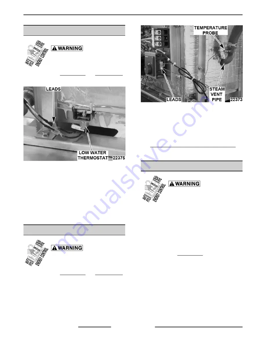
LOW WATER THERMOSTAT
Disconnect the
electrical power to the machine and
follow lockout / tagout procedures.
1.
Remove right SIDE PANEL and REAR PANEL.
2.
Disconnect lead wires.
Fig. 12
3.
Remove low water thermostat.
4.
Reverse procedure to install and check steamer
for proper operation.
A.
Apply small amount of thermal transfer
compound to tip of thermostat.
B.
Apply Loctite 242 to threads of thermostat.
C.
Install thermostat hand tight.
Do not over
tighten.
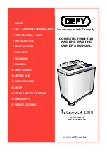
TEMPERATURE PROBE
Disconnect the
electrical power to the machine and
follow lockout / tagout procedures.
1.
Remove right SIDE PANEL and REAR PANEL.
2.
Disconnect probe leads from the temperature
control.
Fig. 13
3.
Remove temperature probe from steam vent
pipe.
4.
Reverse procedure to install replacement probe
and check steamer for proper operation.
5.
Adjust temperature control as outlined under
TEMPERATURE CONTROL CALIBRATION in
SERVICE PROCEDURES AND
ADJUSTMENTS.
HEATING ELEMENT ASSEMBLY
Disconnect the
electrical power to the machine and
follow lockout / tagout procedures.
Removal
The heating element assembly contains elements
molded into a cast aluminum block. The block is
mounted on the underside of cooking compartment.
Heating element assembly sits on springs which
compress to hold assembly tight to bottom surface of
steam chamber but allow for thermal expansion and
contraction.
1.
Remove right SIDE PANEL.
2.
Remove screw and heat shield.
C24EO SERIES ELECTRIC COUNTERTOP STEAMERS - REMOVAL AND REPLACEMENT OF PARTS
F25386 (0415)
Page 8 of 27


