


ER SERIES FRYER SERVICE MANUAL SUPPLEMENT - ELECTRICAL OPERATION
F24696 (May 2001)
Page 9 of 56
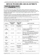
Power up Diagnostics
On power up, the control will execute a self check. The failure of any of these tests will result in the message
“CALL SERVICE” or “MICRO FAIL” being displayed.
This prompt will flash at approximately a 1 hertz rate. While the prompt is displayed, the computer will not
function. If the failure is in the computer, the fryer will operate in backup mode.
When the fryer computer comes out of initialization and self check routines, it will either enter the heating mode
or the melt mode (if programmed) of operation.
For a split vat fryer, one vat can be OFF while the other is in operation. If this occurs, the side that is OFF will be
indicated by displaying the OFF prompt to the user. The message will be on the side of the display which
corresponds to the vat which is OFF.
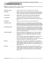
System Tests
The system diagnostics menu is intended to give you the ability to test the basic parts of the computer. It can be
entered by pressing the 8 and 9 product keys simultaneously while turning on power to the fryer computer. The
message "SYSTEM TESTS" is displayed. In this mode you can select one of three tests.
With DISPLAY TEST displayed, press enter to begin a test, use the up and down arrows to rotate through the
screens. Press exit once to return to the test menu or twice to return to normal operation.
With KEYPAD TEST displayed, press enter to begin the test. The control will respond by displaying the name of
the key pressed. Press exit once to return to the test menu or twice to return to normal operation.
With VER xxx displayed, the release number is displayed as "VER XXX".
ELECTRICAL OPERATION
SEQUENCE OF OPERATION
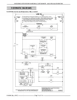
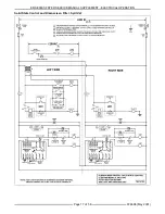
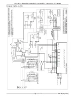
Solid State Fryer Control, Full Vat
Refer to schematic diagram TSP1567C for both the
"Fryer Controls" operation and the "Kleenscreen
Filtering system" operation.
FRY CYCLE - LIQUID FRYING OIL
NOTE: If using solid shortening, refer to "MELT
CYCLE - SOLID SHORTENING" in this section.
1.
Conditions.
A.
Fryer connected to correct supply voltage
(separate connections are required for
each section of the battery).
1)
208, 240 or 480VAC - power for
heating elements.
2)
208 or 240VAC models - Step down
transformer(s) provide power for the
fryer controls, basket lift(s) if
installed, and the Kleenscreen
filtering controls.
3)
480VAC models - A separate
120VAC connection is used along
with step down transformer(s) to
provide power for the fryer controls,
basket lift(s) if installed, and the
Kleenscreen filtering controls.
4)
All models require a separate
120VAC connection for the pump
motor.
B.
24VAC transformer energized.
C.
Fryer properly grounded.
D.
Internal fryer circuit breakers ON.
NOTE: 208 and 240VAC models at 21 and 24
KW only.
E.
Power switch to the fryer section controls
in center NEUTRAL (starting) position.
F.
Tilt switch contacts CLOSED (N.O. - held
CLOSED with heating elements down).
G.
Second high limit thermostat CLOSED.
H.
Frying oil at the proper level in vat and
below 300°F.
I.
Fry/Melt switch in FRY position.
J.
Temperature control set to desired frying
temperature.
Содержание 126905
Страница 26: ...ER SERIES FRYER SERVICE MANUAL SUPPLEMENT ELECTRICAL OPERATION F24696 May 2001 Page 26 of 56 ...
Страница 27: ...ER SERIES FRYER SERVICE MANUAL SUPPLEMENT ELECTRICAL OPERATION F24696 May 2001 Page 27 of 56 ...
Страница 28: ...ER SERIES FRYER SERVICE MANUAL SUPPLEMENT ELECTRICAL OPERATION F24696 May 2001 Page 28 of 56 ...
Страница 29: ...ER SERIES FRYER SERVICE MANUAL SUPPLEMENT ELECTRICAL OPERATION F24696 May 2001 Page 29 of 56 ...
Страница 30: ...ER SERIES FRYER SERVICE MANUAL SUPPLEMENT ELECTRICAL OPERATION F24696 May 2001 Page 30 of 56 ...
Страница 31: ...ER SERIES FRYER SERVICE MANUAL SUPPLEMENT ELECTRICAL OPERATION F24696 May 2001 Page 31 of 56 ...
Страница 32: ...ER SERIES FRYER SERVICE MANUAL SUPPLEMENT ELECTRICAL OPERATION F24696 May 2001 Page 32 of 56 ...
Страница 33: ...ER SERIES FRYER SERVICE MANUAL SUPPLEMENT ELECTRICAL OPERATION F24696 May 2001 Page 33 of 56 ...
Страница 34: ...ER SERIES FRYER SERVICE MANUAL SUPPLEMENT ELECTRICAL OPERATION F24696 May 2001 Page 34 of 56 ...
Страница 35: ...ER SERIES FRYER SERVICE MANUAL SUPPLEMENT ELECTRICAL OPERATION F24696 May 2001 Page 35 of 56 ...
Страница 36: ...ER SERIES FRYER SERVICE MANUAL SUPPLEMENT ELECTRICAL OPERATION F24696 May 2001 Page 36 of 56 ...
Страница 37: ...ER SERIES FRYER SERVICE MANUAL SUPPLEMENT ELECTRICAL OPERATION F24696 May 2001 Page 37 of 56 ...
Страница 38: ...ER SERIES FRYER SERVICE MANUAL SUPPLEMENT ELECTRICAL OPERATION F24696 May 2001 Page 38 of 56 ...
Страница 39: ...ER SERIES FRYER SERVICE MANUAL SUPPLEMENT ELECTRICAL OPERATION F24696 May 2001 Page 39 of 56 ...
Страница 40: ...ER SERIES FRYER SERVICE MANUAL SUPPLEMENT ELECTRICAL OPERATION F24696 May 2001 Page 40 of 56 ...
Страница 41: ...ER SERIES FRYER SERVICE MANUAL SUPPLEMENT ELECTRICAL OPERATION F24696 May 2001 Page 41 of 56 ...
Страница 42: ...ER SERIES FRYER SERVICE MANUAL SUPPLEMENT ELECTRICAL OPERATION F24696 May 2001 Page 42 of 56 ...
Страница 43: ...ER SERIES FRYER SERVICE MANUAL SUPPLEMENT ELECTRICAL OPERATION F24696 May 2001 Page 43 of 56 ...
Страница 44: ...ER SERIES FRYER SERVICE MANUAL SUPPLEMENT ELECTRICAL OPERATION F24696 May 2001 Page 44 of 56 ...
Страница 45: ...ER SERIES FRYER SERVICE MANUAL SUPPLEMENT ELECTRICAL OPERATION F24696 May 2001 Page 45 of 56 ...
Страница 46: ...ER SERIES FRYER SERVICE MANUAL SUPPLEMENT ELECTRICAL OPERATION F24696 May 2001 Page 46 of 56 ...
Страница 47: ...ER SERIES FRYER SERVICE MANUAL SUPPLEMENT ELECTRICAL OPERATION F24696 May 2001 Page 47 of 56 ...
Страница 48: ...ER SERIES FRYER SERVICE MANUAL SUPPLEMENT ELECTRICAL OPERATION F24696 May 2001 Page 48 of 56 ...
Страница 49: ...ER SERIES FRYER SERVICE MANUAL SUPPLEMENT ELECTRICAL OPERATION F24696 May 2001 Page 49 of 56 ...
Страница 54: ...ER SERIES FRYER SERVICE MANUAL SUPPLEMENT F24696 May 2001 Page 54 of 56 NOTES ...
Страница 55: ...ER SERIES FRYER SERVICE MANUAL SUPPLEMENT F24696 May 2001 Page 55 of 56 NOTES ...


