


17
18
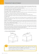
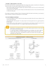
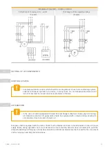
OIMM – VENTUS PRO
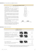
Panel filters and zigzag filters are normally fitted within the unit prior to shipping.
Bag filters are normally shipped in closed carton boxes to avoid any collection of dust and loss of efficiency
prior to commissioning. Each bag filter is housed within a special holding frame with necessary locking spring
to ensure proper sealing.
Automatic roll filters consist of basic frame dispensing unit for clean media, rewind unit for dirty media, drive
system, roll filter media and control system. Normally filter media and control system are supplied loose for
site installation. For assembly, filter media roll is mounted on the dispensing unit taken along the guide channel
through working section and locked to the rewind unit.
Differential pressure switch must be installed and connected to the control panel.
Absolute filters are shipped in sealed carton boxes. While assembly, special care must be taken to ensure that
each filter cell is properly sealed within the assembly frame with no possibility of air leakage.
Other types of filters such as active carbon filters, sand filters etc. are supplied with manufacturer’s instructions
along with the units.
Filters that are shipped separately in the unit should be assembled after cleaning the inner surface by operating
the fan. Before start-up, make sure that filters are properly installed.
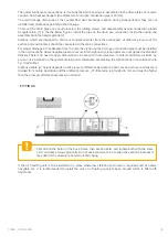
All coils are leak tested and checked prior to assembly. Fins are checked for proper condition. However, they
must be checked once more and combed out if necessary, because they might be damaged during handling and
installation. Do not remove plastic covers from coil pipe connections until the unit is ready for piping connectors.
Connections should be checked according to the project and the leakage should be taken in to account. System
layout should take into consideration of possible coil withdrawal.
It is recommended that the water flow is shut off when the fan is switched off. To avoid the overheating of the
heating coil, the hot water pump and water / steam valves should only be opened during the operation of fan.
Supply air control: The supply air temperature of the coil at the suction side should be max. 40˚C, otherwise the
overheating danger will occur.
Check the concentration ratio of the antifreeze before the start-up of the cooling coil. It should be enough for the
claimed operating temperature range. It should be taken in to account that the increasing concentration ratio of
the antifreeze decreases the performance of the coil.
The minimum temperature of the chilled water should be +20C, at lower temperatures freezing danger will occur.
Antifreeze is a dangerous chemical. The safety regulations of the antifreeze manufacturer should be taken in to
account.
Direct expansion coils will be supplied with a refrigerant distributor suitable for brazed connections. Refrigerant
pipe work must include necessary shut off devices, dehydrators, solenoid valves, oil traps etc. Selection, sizing,
installation and setting of thermostatic expansion valve should be in accordance with the recommendation of
condensing unit manufacturer.
Steam coils: Special care should be taken for collection and disposal of condensate within the coils and to
prevent entry of the condensate in the main into the coil by trapping it independently on a coil bypass. Condensate
connections to the stream trap must be of the same size as the coil outlet.
AIR FILTERS
COIL HEAT EXCHANGERS
3.7.3
3.7.4
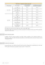
!
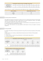
Do not operate coils above the maximum temperature and pressure specified on the capacity
label.
!
If not otherwise stated on the capacity label, maximum operating temperature and pressure:
•
for water coils (type:1) : 90
º
C, 10 bar,
•
for water coils (type:2) : 150
º
C, 15 bar,
•
for steam coils: 160
º
C, 6 bar
!


