


6
• Assembly of the flow meter
The flow meter should be mounted on an easily accessible location, so that
dismantling for cleaning the meter presents no problem . Since flow meters
can work in any installation position and flow direction, you can mount it on
any location of your system . Take care, when installing the flow meter that
liquid always remains in the flow meter, even at system standstill and that it
can never run empty . The outflow of the flow meter should therefore always
show a certain back pressure, since this clamps the flow meter firmly in the
liquid column (the meter supports itself through this on the liquid column)
and the pipe line cannot run empty . In critical cases or when the pipe line
is at standstill or standby and can run empty, we recommend installing an
extra non-return valve in the outflow line .
Flow meters of the “VSI” product line can be mounted directly onto a block
or into the pipe line using four screws . Always select large cross sections
for the hydraulic supply and return flow respectively for the entire pipe line
system (if possible) . This lowers the fall in pressure and the flow rate in the
total system .
Important:
Make sure that the specified maximum permitted operating pressure of the flow meter
cannot be exceeded, whatever the operating mode of the system. Note the flow meter
range that is dependent on the viscosity of the fluid to be measured.
Important:
Make sure that the flow meter is always completely filled both in inflow and outflow
and that the outflow has a little back pressure. This prevents the meter being damaged by
a sudden and steep increase of flow and at the same time improves measurement accuracy.
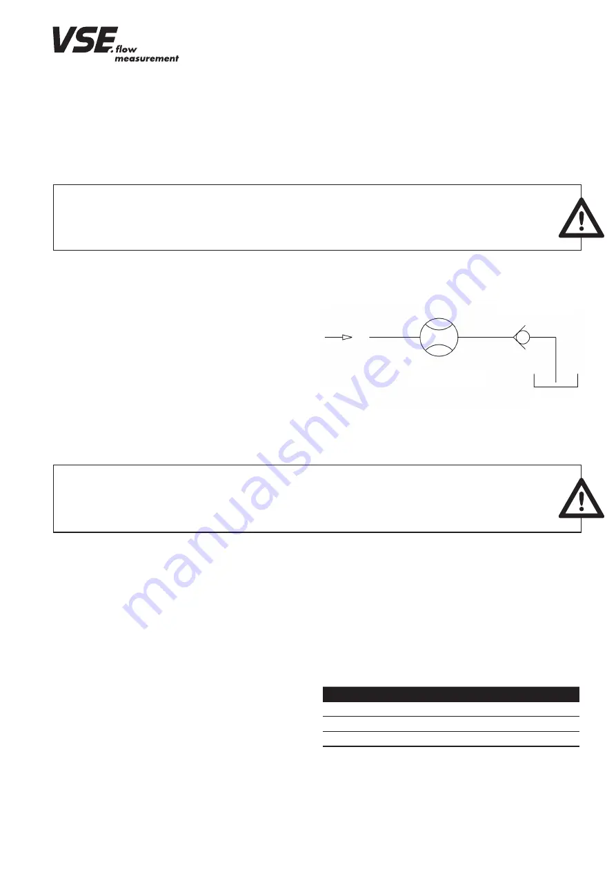
Fig. 1: Flow meter installation with non-return valve
Flow meter, size (cast iron and 1.4305)
torque
VSI 0 .02; VSI 0 .04; VSI 0 .1; VSI 0 .2
15 Nm
VSI 0 .4; VSI 1; VSI 2
35 Nm
VSI 4
120 Nm
VSI 10
250 Nm
VSE supplies subplates for all flow meters of the “VSI” product line; they
have various pipe threads and side or rearside connection (see subplates
data sheet) . Depending on the provided conditions, the installed pipe line,
the pipe cross section or pipe thread, the operator can choose the suitable
subplate and incorporate this into the system or machine without additional
reductions .
The flow meter is screwed onto the block or subplate with four DIN 912
cheese head screws . The screws are to be evenly pre-tensed crosswise with
the following torques .
When changing the fastening screws you must take great care that the
screws are of property class 10 .9 and 12 .9 .
Block assembly:
The flow meter is directly mounted onto a subplate or manifold, extra
components are not needed . The block contains the hydraulic supply and
outflow of the flow meter and the fixing bore holes (see flow meter
dimension sheet) .
table 1: torque of fastening screws
Please note the special instructions for mounting sizes VSI 4 and VSI 10
(see appendix)
• Flow meter range
The flow meter range specified in the flow meter data sheet (Q
min
- Q
max
)
refers to the testing fluid “hydraulic oil“ with a viscosity of 21 mm
2
/s at a
temperature of 20°C . For this flow meter range, VSE specifies measurement
accuracy of up to 0 .3% of the measurement value and a repetition accu-
racy of 0 .05% .
For fluids of lower viscosity (< 21 mm
2
/s) measurement accuracy deteri-
orates, while for fluids of higher viscosity (> 21 mm
2
/s) it can improve .
Also note, however, that the flow meter range is restricted in case of higher
viscosity (see flow meter data sheet) .
Non-return valve
Flow meter
Tank


