


5
5
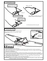
Bottom view
Cut away only the
covering both the
left and the right
side.
A B
C = C’
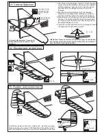
13- Vertical Stabilizer
C
C’
Securely glue together. If coming off
during flight, you lose control of your
air plane.
!
1-Trial fit the vertical stabilizer in place . Check the align-
ment of the vertical stabilizer. When you are satisfied
with the alignment, use a pencil to trace around the
right and left of the stabilizer where it meets the
fuselage.
2-Remove the vertical stabilizer from the fuselage.
Using the sharp hobby knife, carefully cut away the
covering inside the lines which were marked above.
3-Spread epoxy (30 minute) onto the right and left and
bottom of the vertical stabilizer along the area where
the covering was removed and to the fuselage where
the vertical stabilizer mounts.
4-Install the vertical stabilizer into the fuselage and adust
the alignment as described in steep 1.
Both the left and
the right side.
A B
Plastic control horn
....................2
2x12mm screw
..............4
14- Elevator and control horn
3/8 in. (9.5mm)
Trial fit the elevator control horn in place and , mark the mounting
holes positions with a pencil. Drill 5/64”(2mm) through the rudder
and each elevator. Attach the control horns using 2x12mm screws.
2mm
5/64”
IMPORTANT: Please do not clean off the excess epoxy on the stabilizer
and fuselage with strong solvent or pure alcohol, only use kerosene to
keep the colour of your model not fade.
Plastic control horn
....................1
2x12mm screw
..............2
Nylon pushrod
exit guider
CA
CA
Thin CA
Thin CA
15- Rudder and control horn