
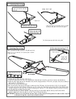


Aileron servo
2mm screw
Aileron
pushrod
Install one clevis onto each of the
aileron control horn. With the aileron
and the aileron servo in the neutral
position, mark the position where
each of the aileron pushrod will
attach to the servo arm. A small
piece of masking tape works well for
this.
Cut off the excess length of each rod.
BOTTOM VIEW
Connect the aileron extension cord to the
aileron servo and secure with adhesive tape
before install the aileron servo on to the wing.
Do the same way with second aileron servo.
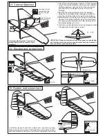
-Switch on the radio (trims centered)
then mount the ailerons servo horn in
neutral position.
-The servo horn should be
perpendicular to the servo.
YES
NO
Hinge Line/Control horn Alignment
Depending on the position of the linkage, determine the location
of aileron control horn.
The horn holes must be perfectly aligned with the axis of articulation.
Mark the position of the “foot” of the horn on the aileron. Then, with
the drill, make the 2 holes.
Install the aileron control horn as shown.
Plastic control horn
....................2
2x20mm screw
..............4
Connector
......2
Aileron push rod
......2
..2
Adhesive
tape
BOTTOM VIEW
Do the same way with second aileron servo.
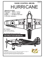
9- Aileron servo
10- Aileron linkage