


© 2019 VPInstruments | MAN-VP-SPRO-EN | Revision: 1901 | Date: 04-07-2019
10
5
Measurement
For all parameters the update interval is 1 second. Within this second, multiple samples are taken
and averaged to provide a stable and reliable output.
5.1
Flow
The VPFlowScope probe uses our proprietary insertion type thermal mass flow sensor. There is no
bypass flow, which results in a high robustness and less sensitivity for dirt or particles. The flow
sensor is directly temperature compensated.
The sensor response signal is directly related to
the mass flow rate and can be described by the
following formula:
Vout = k *λ* ρ * v * (Ts-Tg)
Vout = output voltage
k = sensor (geometrical) constant
λ = thermal conductivity of the gas
ρ = density of the gas
v = actual velocity in m / sec
Ts = sensor temperature
Tg = gas temperature
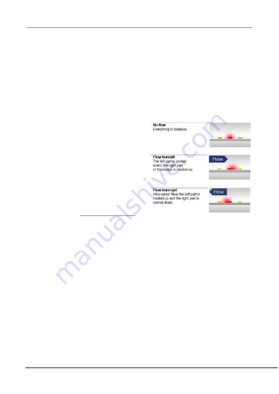
The optional bi-directional sensitivity is shown in
the picture on the right. In bi-directional mode the
negative flow value will show up as a minus sign.
The 4 .. 20 mA value needs to be adapted to suit
the application.
5.2
Pressure
The VPFlowScope probe features a built-in gauge pressure sensor. The sensor range is 0 .. 16 bar |
0 .. 250 psi gauge. The sensor cannot measure vacuum, please contact us if you have a vacuum
application. The sensor membrane can handle media which are compatible with glass, silicon,
stainless steel, Sn/Ni, plating and An/Ag solder.
The sensor signal is sampled with 16 bits. The practical resolution is 0.24 mbar on the 0 .. 16 bar
scale, which is equal to 0.004 psi on the 250 psi scale
5.3
Temperature
The built in temperature sensor measures the compressed air/ gas temperature. The signal is
sampled with 16 bits. The resolution is less than 0.1 °C.
In a vertical pipe, with flow going down, the temperature sensor may heat up at zero flow conditions,
due to the heated flow sensor element. This effect will disappear as soon as there is consumption.
For optimal measurement performance, the VPFlowScope probe needs to be in a stable temperature
environment. When exposed to quick temperature changes or large temperature changes (for
example taking the unit from outdoor to indoor during winter time, or when mounted downstream of a
heat regenerated drier) the temperature compensation may lag behind, which may result in
significant measurement errors.