


10
ca1155E rev B.
5
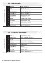
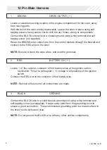
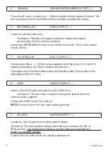
ORANGE
GROUND WHEN ARMED OUTPUT ( - )
This wire will have a continuous ( - ) 300mA output when the system is Armed. This
wire is typically used for controlling window modules or additional sensors.
9
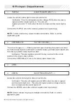
YELLOW
IGNITION INPUT ( + )
Locate the vehicle’s ignition wire at the ignition switch.
Verification:
This wire registers voltage when the key is turned to the ON (or
RUN) position. The voltage does not drop out when the key is turned to the
START (or CRANK) position.
Connect the YELLOW wire to the vehicle’s Ignition wire.
8
GRAY
HOOD PIN INPUT ( - )
Install a Hood Pin Switch and connect to the GRAY wire.
Verification:
This wire when connected will register ground when the
vehicle’s hood is opened.
Connect the GRAY wire to the hood pin.
NOTE:
Be sure to loom the wire, and seal the grommet.
6
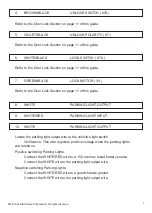
BROWN/BLACK
HORN OUTPUT ( - )
Locate the vehicle’s horn wire.
Verification:
This wire will register at positive voltage and register
ground when the horn switch is pressed.
Connect the BROWN/BLACK wire to the vehicle’s horn wire. This is a low current
output, 300mA.
7
VIOLET/BLACK
AUX 1 OUTPUT ( - )
This wire provides a ( - ) 300mA output capable of driving relays. For Control of
optional accessories (i.e. Power Window/Sunroof, etc.).
To activate refer to the transmitter button configuration chart. Please refer to the
selectable options for timing.