20
2.
Instead of using the white wire you could put a pull-down resistor between the PGM/LVP
pin of your target chip and ground. A value of 10 .. 100 k
Ω
should work fine.
3.
If your Wisp648 was bought ready-made you can contact me to have it replaced by a
corrected version.
4.
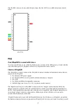
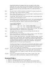
You could repair the PCB. This requires cutting two traces and soldering one wire. The
pictures below show the steps. This is probably best done after the board is assembled.
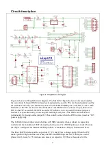
Cut the two PCB traces at the
indicated places.
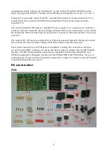
Now only the diagonal trace
connects to the PCB pad.
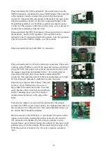
Use a short piece of wire to
connect the two pads that were
previously connected.
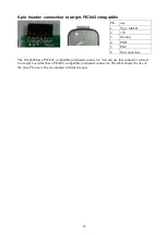
This is what the result should look
like.


