• Make sure the electrical grid data correspond to the data on the rating label of the product
(Fig.B)
Installation
Typical applications Fig. A
Installation process (Fig.1 - 24)
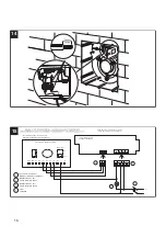
Electrical connections
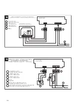
Wiring diagrams (Fig. 15 - 20)
Initial settings
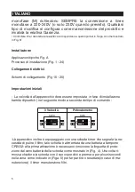
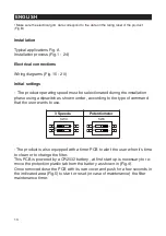
- The product operating speed must be selectionated during the installation
phase using a dipswitch as shown under , according to the type of command
that the user wants to use.
- The product is also equipped with a timer PCB to alert the user when it’s time
to clean or to change the filter.
This PCB is powered by a CR2032 battery , at first start up is necessary to re-
move the protection plastic tab from the battery as shown in (Fig.4).
Once removed close the PCB with its own cover and push for a few seconds in
the indicated area (Fig.5) to start or reset (in case of maintenance) the filter
maintenance timer.
10
3 Speeds
Potentiometer
1
2
SW3
O
N
1
2
SW3
O
N
ENGLISH
Содержание VORT PRESS 240 I
Страница 13: ...13 1 A B FIGURE...
Страница 14: ...14 2 3 5 PULL 4 6 7...
Страница 15: ...15 8 9 10 11 12 13...
Страница 20: ...20 25 26 27 28 29...
Страница 22: ...Note...
Страница 23: ...Note...
Страница 24: ...Note...
Страница 25: ......


