Group 72
Service Procedures
6
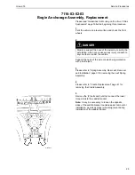
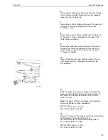
Remove the (4) flange nuts that mount the rear V Torque
rod to the axle mounted bracket and cut any clippings
loose from the V Torque rod.
7
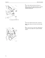
Remove the (4) bolts that mount the rear V Torque rod to
the upper V Torque rod brackets and lift the rear
V Torque rod out.
8
Remove the (2) bolts that mount the front V Torque rod
to the upper V Torque rod bracket on the side of the
vehicle being worked on.
9
Remove the bolts that mount the upper V Torque rod
bracket to the frame rail and remove (2) bolts to the
saddle bracket to assist in the removal of the upper
V Torque rod bracket.
10
W6001323
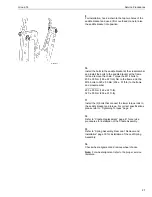
Once all bolts are removed, slide the upper V Torque
rod bracket out from in between the frame and the
crossmember.
11
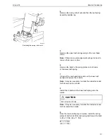
Slide the replacement upper V Torque rod bracket into
place and start all bolts. Torque M14 bolts to 200 ± 30
Nm (148 ± 22 ft-lb) and M16 bolts to 320 ± 50 Nm
(236 ± 37 ft-lb).
Note: The upper V Torque rod bracket is marked with
directional arrows for proper installation.
200 ± 30 Nm (148 ± 22 ft–lb)
320 ± 50 Nm (236 ± 37 ft-lb)
12
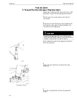
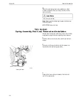
Set the V Torque rod into place and start the (4) bolts and
(4) flange nuts. Torque the M16 bolts to
320 ± 50 Nm (236 ± 37 ft-lb) and the flange nuts to
310 ± 50 Nm (228 ± 37 ft-lb).
320 ± 50 Nm (236 ± 37 ft-lb)
310 ± 50 Nm (228 ± 37 ft-lb)
29
Содержание Group 655-601
Страница 1: ...Service Manual Trucks Group 655 601 Rear Suspension T Ride VN VHD PV776 TSP142921 ...
Страница 2: ......
Страница 4: ......
Страница 6: ...2 ...
Страница 8: ...4 ...
Страница 12: ...8 ...
Страница 19: ...Group 72 Design and Function W6001328 Bogie Bracket and Cradle Assembly 15 ...
Страница 22: ...18 ...
Страница 53: ...49 ...


