65
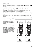
n) Phase Test
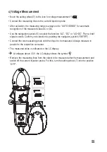
• Move the setting wheel (7) to the icon for power measurement “
” (VC732) or “
”
(VC731).
• For the phase test, select the symbol “
” with the navigation joystick (5). Confirm
your selection by pushing the navigator joystick (“ENTER”).
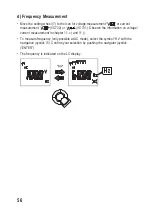
• Connect the red measuring line to phase 1 and the black one to phase 3. Two brief
signals sound. Quickly switch the red measuring line to phase 2.
• The LC display shows “123” for a clockwise- and a “321” for a counterclockwise-rotating
field.
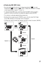
• For voltages of >1000 V, “OLU” appears in the LC-display. For voltages of <30 V, “LoU”
appears.
• If „- - - -“ is visible on the display,
then value is not recognized by the
meter.
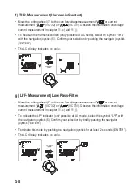
• If the frequency is >65 Hz or
< 45 Hz, “outF” appears in the LC
display.
• After a short time, the LC display
shows the measured result.
• Remove the measuring lines from
the object to be measured after the
measurement and switch off the
current injection probe. For this,
turn the setting wheel (7) into the
position “OFF”.

