Functional Description
The DC output of the power supply unit is electrically isolated and features protective separation from the
mains voltage.
A controllable low voltage protection is provided at the output. The control buttons are digitally controlled and
when a button is pressed direct adjustment of the individual digits is made possible. A turn in a clockwise
direction increases the adjustment value.
It is also possible to continuously adjust the current limit. A jumper at the output is not needed for the adjust-
ment of the current. A turn in a clockwise direction increases the adjustment value.
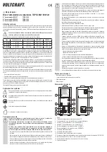
The momentary output voltage (V) and the output current amperage (A) is shown in the display (1).
A secondary side DC connection is possible via two coloured 4mm safety sockets (4 and 5).
Two USB loads can be connected to the two high-power USB outputs AUX.1 and AUX.2, regardless of the
regulated laboratory power pack.
The power supply unit is cooled passively through convection. Therefore, ensure sufficient air circulation
and space on the side.
If the preset current limit is exceeded through overload or short-circuit, then this is sig-
nalled via the “C.C.” display. It will electronically reduce the output voltage to avoid dam-
age to the power supply unit.
Start-up
a) General information
• To operate the power supply unit you need a mains lead containing a protective earth wire, which is inclu-
ded. Use only this one or an identical mains cable. Connect the mains lead to the IEC input (11) on the rear
of the power supply unit and plug the mains plug into an earthed mains socket.
• The power supply unit is not a charger. To charge batteries, use suitable chargers with a charging current
cut-off.
• Always turn the device off when it is not in use.
b) Setting the output voltage
• Ensure that there are no loads connected to the mains power supply.
• Switch on the mains power supply at the power switch (13). The display is illuminated.
• Make sure that the „C.V.“ indicator is on. If this is not the case and indicator „C.C.“ is on, turn the current
adjustment control „CURRENT“ (7) in a clockwise direction.
• Turn the adjustment control „VOLTAGE“ (6) to roughly to the desired output voltage. Access the fine
adjustment menu by briefly pressing on the control button (6). The first decimal of the voltage „V“ starts
flashing. The value of this decimal can be changed by turning the control button.
• Switch to the next decimal by pressing the button again briefly. Make the adjustment until you reach the
desired voltage value.
• Wait a few seconds and the laboratory power pack returns to the normal setting.
c) Setting the current limitation
• Adjust the output voltage as described above.
• Turn the adjustment control „VOLTAGE“ (7) roughly to the desired current limit. Access the fine adjustment
menu by briefly pressing on the control button (7). The first decimal of the current indicator „A“ starts
flashing. The value of this decimal can be changed by turning the control button.
• Switch to the next decimal by pressing the button again briefly. Make the adjustment until you reach the
desired current value.
• Wait a few seconds and the laboratory power pack returns to the normal setting. The current indicator
shows 0.000 A.
• To check the setting for the current, briefly press and thecontrol button „Current“ (7). The value of the
current limit is briefly displayed.
• If no current limit is needed, ensure that it is always set to the highest current value so that operation of
the power supply is not reduced.
d) Enabling/disabling outputs
• The adjustable output and the two USB outputs are enabled and disabled by pressing a button on the
power pack.
• The status is shown by two symbols on the display:
Control indicator for disabled output
Control indicator for enabled output
• By briefly pressing the „OUTPUT“ button (2), you can switch the adjustable output on or off.
• By pressing on the „OUTPUT“ button (2) for approximately 3 seconds will disable all outputs (control output
and 2x USB). Briefly press the „OUTPUT“ button (2) will again enable all outputs.
Connecting a consumer load
Make sure that the load is switched off when being connected to the power supply unit. If
the load is switched on, it can cause sparking while connecting to the sockets. This can
damage the sockets, as well as the connected cables.
• Verify that the correct output voltage has been set on the power supply unit.
• Connect the positive terminal (+) of the load with the red socket „+“ (5) and the negative terminal (-) of the
load with the black socket „-“ (4).
• The connection is made using standard 4mm plugs. You can also use isolated laboratory plugs.
• The green earthing potential socket (3) is connected to the earthing conductor directly. The adjustable
output can be used with the positive terminal to ground reference, or the negative terminal to ground
reference or floating.
• Enable the output on the power pack by pressing the „OUTPUT ON / OFF“ (2) button.
• Switch the consumer on. The current indicator „A“ (7) displays the current that the connected load draws.
USB loads
• You can connect USB loads via the two USB sockets „AUX.1“ and „AUX.2“ regardless of the adjustable
output. Note, however, the max. power consumption of the USB loads.
• You can check the current output to the USB sockets (8/9) via the indicator „AUX.1“ for USB output
„AUX.1“ and the indicator „AUX.2“ for output „AUX.2“. Current is displayed in Ampere „A“.
Maintenance and Cleaning
Always unplug the power plug from the mains socket before cleaning the device.
Except for replacing the fuse and occasional cleaning, the power supply unit does not require any mainte-
nance.
Use a dry, clean, lint-free, antistatic cloth to clean the device. Do not use any abrasive or chemical agents
or detergents containing solvents.
Replacing the Fuse
• If it is no longer possible to switch on the power unit, the mains fuse is probably
defective.
• Proceed as follows to replace the mains fuse:
• Turn off the power supply unit and remove all connecting cables from the unit.
Pull the mains plug from the rear connection (11).
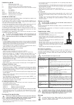
• Remove the rear fuse holder (10) with a suitable screwdriver from the bracket,
as displayed.
• Replace the defective fuse with a new fine-wire fuse (5x20 mm) of the same
type and rated current: Please refer to the Technical Data or the labels on the
device for the security value.
• Push the fuse carefully into the fuse holder.
Troubleshooting
By purchasing this power supply unit you have acquired a product that has been designed to the latest state
of the art and which is operationally reliable. Nevertheless, problems or faults may occur. Therefore, we
would like to describe here how to eliminate possible faults:
Always observe the safety instructions!
Problem/event
Solution/explanation
The display is not illuminated.
No mains voltage?
• Check the safety switch for the mains socket
• Check whether the mains plug is seated correctly in the mains socket
• Check the mains fuse in the power supply unit.
Connected loads don't work.
Correct voltage set?
Is the polarity correct?
Has the power supply overloaded or is the current limitation (display
"CC") active?
Check the technical data of the load.
Output switched off manually?
There is no voltage from the
power pack.
The power supply unit has overheated.
• Remove the load from the power pack and let the power pack cool
off for at least 30 min. The power pack will automatically enable the
output again once the correct operating temperatures are reached.
Check the technical data.
The "CV" indicator is lit
The power supply unit is working in the normal constant voltage
mode.
The "CV" indicator is lit
The power supply unit is working in the normal constant voltage
mode. Check the load's power consumption or increase the current
limit.
Repairs other than those described above should only be performed by an authorised
specialist. Check the technical safety of the device on a regular basis e.g., for damage
to the housing, etc. Any changes and repairs you make on the device will render the
guarantee/warranty null and void.
Disposal
Electronic products are recyclable material and do not belong in the household waste. Dispose
of an unserviceable product in accordance with the relevant statutory regulations.


