


Modular IoT Gateway User Guide
V1R1
www.volansys.com
I Email:
Copyright
©
2017 VOLANSYS
Page |
12
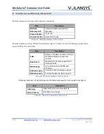
Follow below steps to enter into serial download boot option:
Make SW01 setting as per Table-3
Modify jumpers setting for USB-2 to enable device mode operation as shown in Table- 5
Connect Standard USB type-A to type-A cable with USB-2 (J17) connector.
Power up the device
3.2.2
Internal Boot
Typically, internal boot is selected for normal boot.
Module supports NAND flash and micro SD card as Boot Device. To select the boot device it is required
to configure external BOOT configuration resistors as shown in below table.
BOOT
Device
Configuration
Micro SD
Populated Resistors:
R50, R57, R68, R56, R54, R64, R70, R69, R72, R58, R73, R60, R74, R61, R118,
R133
DNP Resistors:
R59, R71, R127, R120, R136, R121, R123, R140, R134, R135, R132, R119, R131,
R117, R130, R116
NAND
Populated Resistors:
R50, R57, R68, R56, R64, R70, R69, R59, R58, R71, R73, R60, R74, R61, R123,
R132
DNP Resistors:
R54, R72, R127, R120, R136, R121, R140, R134, R135, R118, R119, R133, R131,
R117, R130, R116
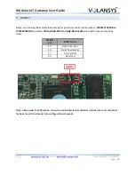
Table 4 - i.MX6 Ultra Lite SOM BOOT Device Configuration
Configuration resistors position on SOM Board is show in below images:


