10
24/28/bi
24/28/bi
24/28/bi
24/28/bi
24/28/bi
4.5.2
CONCENTRIC VERTICAL FLUE
The Rain/Rain bi appliance can be used with the
standard 60/100mm concentric vertical terminal.
For further details on vertical terminations, please
contact the Vokera technical help-line.
4.5.3
VOKERA TWIN FLUE APPLICATION
The Rain/Rain bi appliance can be used with the
Vokera twin flue system. For further details on
this type of application, please contact the Vokera
technical help-line.
4.6
CONNECTING THE GAS AND WATER
The appliance is supplied with an accessories
pack that contains sealing washers and service
valves. The service valves are of the compres-
sion type. When connecting pipe work to the
valves, tighten the compression end first then
insert the sealing washers before tightening the
valve to the appliance.
NOTE
It will be necessary to hold the valve with one
spanner whilst tightening with another.
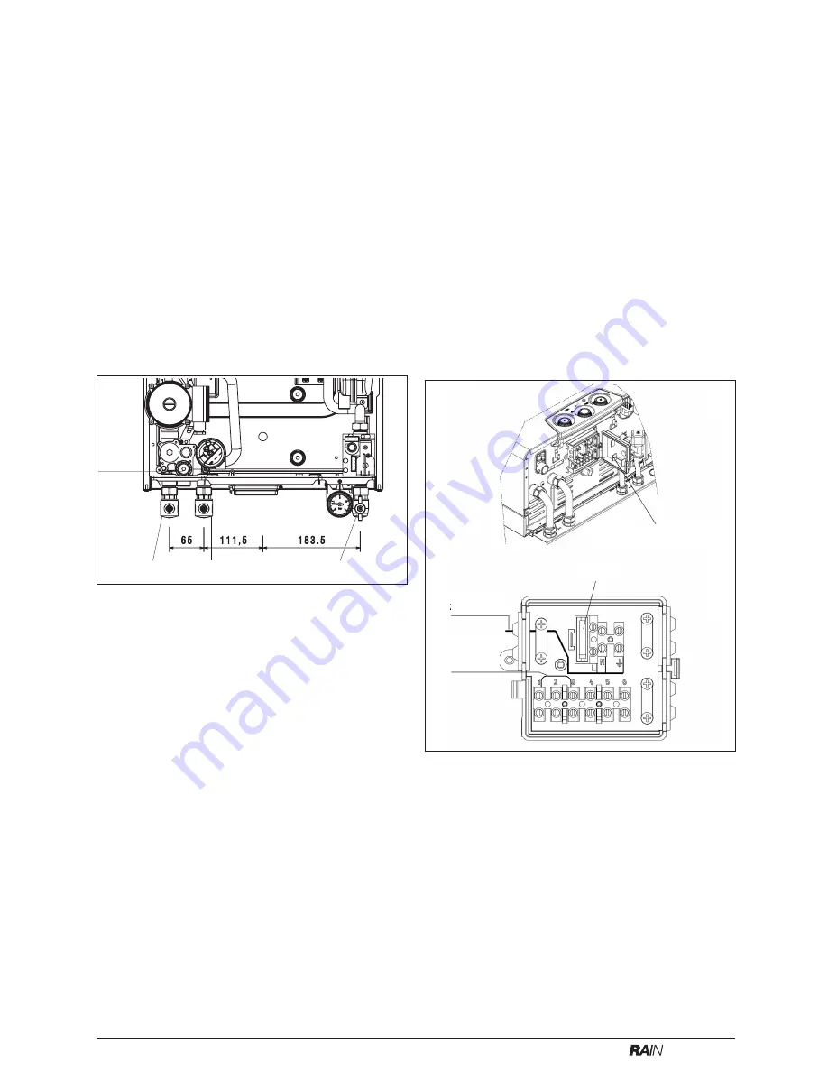
4.6.1
GAS (fig. 9)
The appliance is supplied with a 15mm service
valve, connect a 15mm pipe to the inlet of the
valve and tighten both nuts.
NOTE
It will be necessary to calculate the diameter of
the gas supply pipe to ensure the appliance has
an adequate supply of gas.
4.6.2
FLOW & RETURN (fig. 9)
The appliance is supplied with 22mm service
valves for the flow and return connections, con-
nect a 22mm pipe to the inlet of each valve and
tighten both nuts.
4.6.3
SAFETY VALVE (fig. 9)
Connect the safety valve discharge pipe to the
safety valve outlet and tighten. The discharge
pipe must have a continuous fall away from the
appliance to outside and allow any water to drain
away thereby eliminating the possibility of freez-
ing. The discharge pipe must terminate in a
position where any water - possibly boiling -
discharges safely without causing damage or
injury, but is still visible.
4.7
ELECTRICAL CONNECTIONS
The electrical supply must be as specified in 3.7/
3.7a. The appliance is supplied, pre-wired with a
1.0 metre length of flex, connect the wires as
follows:
Fig. 9
gas
safety
valve
flow
return
●
connect the Brown wire to the L (Live) terminal
of the plug or fused isolator
●
connect the Blue wire to the N (Neutral) termi-
nal of the plug or fused isolator
●
connect the Green/Yellow wire to the E (Earth)
terminal of the plug or isolator
●
ensure the plug or fused isolator is fitted with a
3AMP fuse.
If this method of connection is unsuitable, please
refer to section 8. A qualified electrician should
connect the electrical supply to the appliance. If
controls - external to the appliance - are required,
a competent person must undertake the design
of any external electrical circuits, please refer to
Section 8 for detailed instructions. ANY EXTER-
NAL CONTROL OR WIRING MUST BE SERVED
FROM THE SAME ISOLATOR AS THAT OF
THE APPLIANCE. The supply cable from the
isolator to the appliance must be 3-core flexible
sized 0.75mm to BS 6500. Wiring to the appli-
ance must be rated for operation in contact with
surfaces up to 90 °C.
4.8.1
ELECTRICAL CONNECTION
The appliance terminal strip is located beneath
the appliance control panel (see fig. 10). Locate
and remove the screw that secures the electrical
connection box cover.
NOTE
The appliance comes with a factory fitted link (ter-
minals 1 & 3) to allow basic operation of the boiler
via the selector switch. If external controls are
required please refer to the wiring diagrams in
section 8 for more detailed information.
4.8.2
CONNECTING THE MAINS (230V) INPUT (see
fig. 10)
Remove the connection box cover as described
in 4.8.1. Pass the cable through the cable an-
chorage. Connect the supply cable wires (earth,
Electrical
connection box
2A fuse
230V supply
VF room
thermostat
connection
Fig. 10


