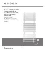
Die Installation und Inbetriebnahme Ihres Designheizkörpers FULDA/GENF
Elektroausführung ist von einer zugelassenen Fachfirma durchzuführen.
Bei der Installation sind die einschlägigen Normen bzw. die nationalen
Sicherheitsvorschriften wie ÖVE- und VDE-Bestimmungen zu beachten.
Vor Montagebeginn berücksichtigen Sie bitte die unter
„WICHTIGE HIN-
WEISE“
angeführten Wand- bzw. Bodenabstände.
Bei der Montage von Heizkörpern ist zu beachten, dass die Befestigung von
Heizkörpern so dimensioniert wird, dass sie für die bestimmungsgemäße Ver-
wendung und vorhersehbarer Fehlanwendung geeignet ist. Hierbei sind insbe-
sondere die Verbindung mit dem Baukörper sowie dessen Beschaffenheit, die
Geeignetheit des Montagezubehöres und die möglichen Belastungen nach
erfolgter Montage zu prüfen.
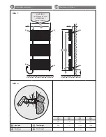
WANDMONTAGE (Abb. 1 und 2):
Aufstecken der beigepackten Blech-
muttern
1
auf die Montagestutzen 2
(Abb. 2).
Anreißen, bohren der Löcher
A
- Bohrer ø10 - und setzen der Dübel ent-
sprechend den Aufhängungsmaßen -
(Abb. 1).
Empfehlung:
Messen Sie bitte vorher zur Heizkörperidentifizierung die Abstands-
maße der Montagestutzen 2 (Abb. 1 u. Abb. 2) nach.
Nach Bedarf (Wandbeschaffenheit) sind die beigepackten Kunststoff-
beilagen
3
auf die Wandfüße
4
zu kleben
(Abb. 2)
. Bitte auf saubere
Klebestellen achten.
Befestigung der Wandfüße
4
und diese waagrecht ausrichten, wobei die
Senklochbohrungen
5
in den Wandfüßen nach außen stehen müssen. Dabei
sollen die Wandmontageschrauben
6
in der Mitte der Langlöcher der Wand-
füße montiert werden. (Es wird empfohlen, das Abstandsmaß der montierten
Wandfüße vor der Heizkörperwandmontage zu kontrollieren.)
Wandmontage des Heizkörpers:
Die Montagestutzen
2
werden in die
Wandfüße
4
gesteckt und mittels Blechschraube
7
miteinander verbunden.
Durch das Langloch im Montagestutzen kann der Wandabstand zur verti-
kalen Ausrichtung des Heizkörpers variiert werden.
Verstellmöglichkeiten
der Wandfüße in Baulängen- bzw. Bauhöhenrichtung sind durch das Lang-
loch in der beweglichen Scheibe
8
im Wandfuß gegeben.
Das Wandmontagekonzept ist ein auf fertige Wände konzipiertes
System.
Folgende Normen sind bei der Montage der Heizkörper unbedingt
einzuhalten:
•
DIN 55900:
Sprühbereich in Nassräumen
•
VDI 2035:
Vermeidung von Schäden in Warmwasserheizungsanlagen
•
DIN 18017 Teil 3:
Lüftung von Bädern und Toiletten ohne Fenster
•
EN 14336:
Heizungsanlagen in Gebäuden, Installationen und Abnahme
der Warmwasserheizungsanlagen
Bei Verwendung dieser Heizkörper zur Raumbeheizung, muss bauseitig ein
programmierbares Temperaturregelgerät gemäß ÖKO-Design-Richtlinie
2018 verwendet werden.
INSTALLATION / MONTAGE FULDA/GENF ELEKTROAUSFÜHRUNG
D
HEIZKÖRPERBESCHREIBUNG
D
Die Elektroheizkörper der Familie FULDA/GENF sind elegante Design-Ba-
dezimmerheizkörper, mit eingebauter Elektroheizung. Das temperatur-
abhängige PTC-Heizelement regelt die Temperatur der Wärmeträger-
flüssigkeit im Gerät eigenständig durch Veränderung des elektrischen
Widerstandes.
Der gleichbleibende hohe Qualitätsstandard unterliegt einer laufenden
Eigen- und Fremdüberwachung.
Your electrical designer radiator FULDA/GENF must be installed and com-
missioned by an authorised company.
All relevant installation standards and national safety regulations such as
the ÖVE and VDE regulations must be complied with.
Before starting installation work please take into account the wall and floor
distances described in the
„IMPORTANT INFORMATION“.
For the correct installation of radiators it is essential that the fixing of the
radiator is carried out in such a way that it is suitable for intended use AND
predictable misuse. A number of elements need to be taken into considera-
tion including the fixing method used to secure the radiator to the wall, the
type and condition of the wall itself, and any additional potential forces or
weights, prior to finalising installation.
WALL INSTALLATION (Abb. 1 and 2):
Place the sheet metal screws
1
provided on the mounting connections 2
(Abb. 2).
Mark and drill the holes
A
- drill ø10 - and position the dowels according to
the suspension dimensions -
(Abb. 1).
Recommendation:
First verify the distance between the mounting connections 2 (Abb. 1
and 2) in order to identify the radiator.
If necessary, (wall condition) stick the plastic shims
3
on the wall feet
4
(Abb. 2).
Please ensure that the adhesion surfaces are clean.
Fix the upper wall feet
4
in a horizontal position making sure that the coun-
tersunk holes
5
in the wall feet are facing outwards. The wall mounting
screws
6
should be mounted in the centre of the oblong holes of the wall
feet. (We recommend that you check the distance between the mounted
wall feet before mounting the radiator on the wall.)
Mounting the radiator on the wall:
Put the mounting connections
2
in
the wall feet
4
and screw them together with the sheet metal screws
7
. The
wall space can be varied by the oblong hole in the mounting connection.
The length and height of the wall feet can be adjusted by means of the
oblong hole in the movable washer
8
in the wall feet.
The wall mounting concept is a system designed for completed walls.
The following standards must be adhered to when installing radiators:
•
DIN 55900:
Spraying area in wet rooms
•
VDI 2035:
Prevention of damage in water heating installations
•
DIN 18017 Part 3:
Ventilation of bathrooms and toilets without windows
•
EN 14336:
Heating systems in buildings. Installation and commissio-
ning of water based heating systems
When using these radiators for space heating, must have a programmable
temperature controller on site according to ECO-Design-Guideline 2018.
The electrical radiators from the FULDA/GENF range are elegant designer
bathroom radiators with integrated electrical heating rods. The tempera-
ture-dependent PTC heating element regulates the temperature of the
heat transfer fluid in the device independently by changing the electrical
resistance.
The consistently high quality standards are subject to continual internal
and external controls.
INSTALLATION / ASSEMBLY FULDA/GENF ELECTRICAL RADIATORS
GB
DESCRIPTION OF RADIATOR
GB
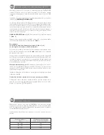
Radiator Sizes, total
length x total height
[mm]
PTC-Electrical heating for
heat transfer fluid 60 °C
500 x 1220
400
600 x 1220
600
600 x 1766
900
Heizkörperdimension,
Baulänge x Bauhöhe
[mm]
PTC-Elektroheizelement bei
Wärmeträgerflüssigkeit 60 °C
500 x 1220
400
600 x 1220
600
600 x 1766
900
Содержание FULDA
Страница 11: ...D NOTIZEN NOTES GB...
Страница 12: ...D NOTIZEN NOTES GB...

