


Vibraon Measurement Instruments
10
2
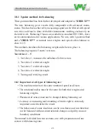
Warning!
Incorrect setting of the emissivity factor
can lead to considerable errors of
measured temperature.
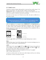
Direct the IR temperature transducer towards the surface you want to measure. Keep a distance of approximately
200-500 mm (8- 20 inches)
between the instrument and the object
. Reduce the distance between the object and the instrument in accordance with the surface size.
Note: when you get the temperature that differs most to the surroundings, then you probably have got the right direction.
The measurement surface size related to the distance 8:1
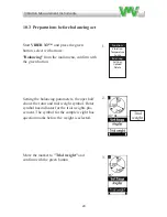
Emissivity:
Set the
coefficient for surface reflection factor
(Emissivity factor) using the table below or check via a contact probe.
Select the item with (UP) and (DOWN) arrow keys.
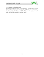
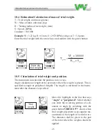
Sound screen
Listening to a machine sounds enables analysis of gears and low speed bearings (<300 rpm) in an alternative way and can improve analysis
speed and quality.
Viber X3™
makes it possible for the user to listen to the machine while at the same time seeing the vibrations in the
instrument display.
Note that you must choose the
Vibration Screen
while the sound is enabled the see the vibration signal.
When a headphone set is connected to the
Viber X3
™, the
Sound Screen
can be used to adjust the sound volume (depending on hardware
version there is also a volume control on the headphone cord). Before changing volume, the
SOUND
function must be
ON
. Sound output
status is enabled (ON) or disabled (OFF) in the
Sound Settings
menu.
Material
Emissivity
factor
Heat sink, black anodized
0.98
Paper
0.97
Black paint, matt
0.97
Ice, smooth
0.97
Wood
0.94
Glass
0.94
Rubber, hard
0.94
Transformer paint
0.94
Concrete
0.93
Brick, mortar, plaster
0.93
Porcelain
0.92
Steel, oxidized
0.79
Cooper, oxidized
0.76
Steel, heat treated surface
0.52
Copper
0.04
Aluminium, bright
0.04
Warning!
To protect your hearing,
y
ou should always remove the headphones from your
ears when you move the sensor or re-connect the cable.
2
War
ni
ng
!
In
co
rrec
t s
etti
ng
o
f th
e em
iss
ivity
fa
cto
r
ca
n l
ea
d to
co
ns
id
er
ab
le e
rro
rs o
f
m
ea
su
red
tem
per
atu
re.
Dir
ec
t th
e IR
te
m
pe
ra
tu
re
tr
an
sd
uc
er
to
w
ard
s th
e s
urf
ac
e y
ou
w
ant
to
m
ea
sur
e. K
ee
p
a di
sta
nc
e o
f a
ppr
ox
im
ate
ly
200-
500
mm
(8-
20
in
ch
es
)
be
tw
ee
n
the
ins
trum
ent
a
nd
th
e o
bj
ec
t
. R
ed
uc
e t
he
d
ista
nc
e b
etw
ee
n t
he
o
bje
ct
an
d t
he
in
str
um
ent
in
ac
co
rda
nc
e w
ith
the
sur
fac
e s
ize
.
No
te
: w
he
n y
ou
ge
t th
e t
em
pe
ra
tu
re
th
at d
iffe
rs m
os
t t
o t
he
su
rro
un
din
gs,
th
en
yo
u p
ro
ba
bly h
av
e g
ot t
he
rig
ht
dir
ec
tio
n.
Th
e m
ea
su
re
m
en
t s
urf
ac
e s
ize
re
la
te
d t
o t
he
dis
ta
nc
e 8:
1
Em
iss
iv
ity
:
Se
t th
e
co
eff
icie
nt
fo
r s
urf
ac
e r
ef
lec
tio
n f
ac
to
r
(Em
iss
iv
ity
fa
cto
r) u
sin
g t
he
ta
ble
be
lo
w
or
ch
ec
k v
ia a c
on
tac
t p
ro
be
.
Se
le
ct t
he
it
em
w
ith
(U
P) a
nd
(D
O
W
N) ar
ro
w
k
eys
.
So
un
d
sc
re
en
Lis
te
ni
ng
to
a
m
ac
hi
ne
so
und
s e
na
bl
es
ana
lys
is o
f g
ea
rs
and
low
spe
ed
be
ari
ng
s (
<3
00
rpm
) in
an
alt
ern
at
ive
w
ay
an
d c
an
im
pro
ve
an
al
ys
is
spe
ed
an
d
qua
lity
.
Vib
er
X3
™
m
ak
es
it
po
ssib
le
fo
r t
he
u
se
r t
o lis
te
n t
o t
he
m
ac
hin
e w
hile
a
t t
he
sa
m
e t
im
e s
ee
ing
th
e v
ibr
atio
ns
in
the
ins
trum
ent
di
spl
ay
.
No
te
th
at
yo
u m
us
t c
ho
os
e t
he
Vib
ra
tio
n S
cr
ee
n
w
hile
th
e s
ou
nd
is
en
ab
le
d t
he
se
e t
he
vib
ra
tio
n s
ign
al.
W
he
n
a he
adpho
ne
se
t is
co
nne
cte
d
to
the
Vib
er
X3
™
, the
So
un
d S
cr
ee
n
ca
n
be
u
se
d
to
adj
us
t t
he
so
un
d
vo
lum
e (
de
pe
ndi
ng
o
n ha
rdw
are
ve
rsio
n t
he
re
is
a
lso
a
vo
lu
m
e c
on
tro
l o
n t
he
h
ea
dp
ho
ne
co
rd
). B
efo
re
ch
an
gin
g v
olu
m
e,
th
e
SO
U
ND
func
tio
n
m
us
t b
e
ON
. S
ound
o
ut
put
sta
tus
is
ena
bl
ed
(O
N)
or
di
sa
bl
ed
(O
FF
) in
the
So
und
Se
tting
s
m
enu.
M
ate
ria
l
Em
iss
ivit
y
fa
cto
r
He
at s
in
k,
b
lac
k a
no
diz
ed
0.
98
Pa
per
0.
97
Bla
ck p
ain
t, m
att
0.
97
Ice
, sm
oot
h
0.
97
W
ood
0.
94
Gla
ss
0.
94
Rubb
er,
ha
rd
0.
94
Tra
ns
for
m
er
pa
in
t
0.
94
Co
nc
re
te
0.
93
Br
ick,
m
ort
ar,
p
las
te
r
0.
93
Po
rce
lain
0.
92
Ste
el,
ox
id
ize
d
0.
79
Coop
er,
ox
id
ize
d
0.
76
Steel
, h
ea
t tr
ea
ted
su
rfa
ce
0.
52
Co
ppe
r
0.
04
Alu
m
in
ium
, b
rig
ht
0.
04
W
arni
ng
!
To
p
ro
te
ct y
ou
r h
ea
rin
g,
y
ou
sh
ou
ld
a
lw
ay
s r
em
ov
e t
he
h
ea
dp
ho
ne
s f
ro
m
y
ou
r
ea
rs w
he
n y
ou
m
ov
e t
he
se
nso
r o
r r
e-co
nn
ect
th
e ca
ble
.
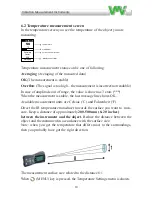
6.2 Temperature measurement screen
I
n the temperature screen you see the temperature of the object you are
measuring.
Temperature measurement status can be one of following:
Averaging
(Averaging of the measured data)
OK
(The measurement is stable)
Overflow
(The signal is too high – the measurement is incorrect/not readable.)
In case of amplitude out of range, the value is shown as 3 stars (***).
When the measurement is stable, the last message line shows OK.
Available measurement units are Celsius (°C) and Fahrenheit (°F).
Direct the IR temperature transducer towards the surface you want to mea
-
sure. Keep a distance of approximately
200-500 mm (8- 20 inches)
between the instrument and the object.
Reduce the distance between the
object and the instrument in accordance with the surface size.
Note: when you get the temperature that differs most to the surroundings,
then you probably have got the right direction.
Auto-shutoff
DISABLED
Settings
20 sec.
Unit
mm/s rms
Range
2-1600 Hz
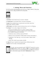
To
exit Setting
s
menu, just press again the
(MENU)
key.
All settings, except disabled transducer power, will be stored into the permanent FRAM memory.
1.1
Temperature measurement screen
In the analysis screen you see the temperature of the object you are measuring. If you have enabled the audio (see audio screen) you may also
at the same time listen to the bearings.
In the upper right corner you will see the battery status and if the charger is plugged in or not.
Temperature measurement status can be one of following:
Ranging
(The instrument is calculating the best measurement range)
Averaging
(Averaging of the measured data)
OK
(The measurement is stable)
Overflow
(The signal is too high – the measurement is incorrect/not readable.)
In case of amplitude out of range, the value is shown as 3 stars (***).
When the measurement is stable, the last message line shows
OK.
Available measurement units are Celsius (°C) and Fahrenheit (°F).
Stability bar
Temperature
Current emissivity factor
Measurement status
NOTE: As default, when the instrument starts, the transducer power is ENABLED.
Selected item
The measurement surface size related to the distance 8:1
When (MENU) key is pressed, the Temperature Settings
menu is shown.
Содержание VIBER X3
Страница 2: ......
Страница 38: ...Vibra on Measurement Instruments 36...
Страница 39: ...Vibra on Measurement Instruments 37...
Страница 41: ...Vibra on Measurement Instruments 39...
Страница 43: ...Vibra on Measurement Instruments 41...
Страница 46: ...Vibra on Measurement Instruments 44 Click on next...
Страница 48: ...Vibra on Measurement Instruments 46 Click on next...
Страница 58: ...Vibra on Measurement Instruments 56...
Страница 59: ......


