v8.05 - Depósito legal y Copyright 2008. Todos los derechos reservados.
VMB ESPAÑOLA, S.A.
4. INSTRUCTIONS.
4.1 -
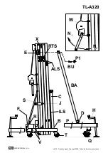
Situate the lift on its transport wheels (
T
)
upon a flat and stable surface.
When erecting the lift in open air, the risk of
wind is prevalent.
Where wind speeds exceed 30 Km/h it is
essential to tie the lift. 2 lateral fixing points (
X
)
are situated at the top of profile 2, where
tensors should be attached and fixed on secure
and firm ground (NEVER ON A VEHICULE OR
ANYTHING THAT CAN MOVE).
4.2 –
Remove the outriggers from their
transport compartments (
S
) and place them in
the working position (
V
) ensuring they are fixed
with the security locks (
R
). The long outriggers
are placed and the front beneath the load. The
short outriggers are placed at the back.
4.3 –
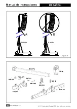
Remove the front support bars (
BA
) from
their transport compartment (
S
) and place them
in their corresponding fixed position (
D
) on each
front outrigger and at the top of the first profile
(
E
) ensuring they are fixed with the pins
provided
P1
.
To correctly fix the front support bars (
BA
),
adjust the support of the front outrigger by
turning the stabiliser handel in the necessary
direction.
Insert clips (
BU
) and security pins (
P1
).
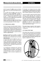
Adjust the vertical position of the lift with the
stabilisers (
Q
) turning the handels so that the
spirit level is centred (
F
).
4.4 –
Let go of transport security
B
, remove
the forks and place them horizontally.
Place the lifting carriage at the required height
so that the Line Array buffer can be attached.
The careful positioning of the front outriggers
enables the Line Array to fit between them and
ease assembley on to the forks.
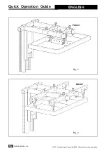
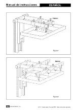
Support
FAS-01
is to be fixed to the forks by
either 1 or 2 points. See fig.
1.
If the Line Array Buffer has 4 link points use
the
FAS-02
support which enables the Line
Array to be flown from 4 points, see fig.
2.
Both supports
FAS-01
and
FAS-02
are inserted
on the forks as follows:
The Line Array cabinets will be attached to their
buffer with the angles calculated according to
the acoustic coverage required.
This ensures the Line Array cabinets can be
curved in function with the necessary degrees
required between them.
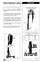
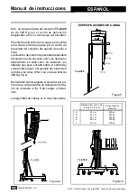
The system should be attached at the
necessary distance to achieve the required
curve. The last cabinet should not hit the body
of the lift. See fig.
3.
To ensure the maximum security margin it is
necessarry to always attach the Line Array at
the minimum distance possible from the body
of the lift. This will mean that the bottom cabinet
is as close as possible to the body of the lift.
See fig.
3A
.
To avoi d overloading do not seperate
uneccessarily the Line Array from the body of
the lift. See fig.
3B
.
Quick Operation Guide
ENGLISH
Содержание TL - A320
Страница 40: ......


