


VMAC – Vehicle Mounted Air Compressors
Toll Free:
1-800-738-8622 Local: 1-250-740-3200
Fax: 1-250-740-3201
39
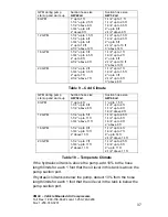
Temperate Climate
Not Critical. Size as per Table 10
GPM during pump
start-up and warm-up
Return line size
(AW 22oil)
Return line size
(AW 32 oil)
8 GPM
3/4”
3/4”
12 GPM
3/4”
3/4” up to 11ft
1” above 11ft
Cold Climate
16-20 GPM
1”
1”
No Tank Preheat –
Line sizing here is
based on strict
adherence to Note 1
of Table 1
Not critical. Size as per Table 3.
GPM during
pump startup and
warm-up
Return line size
8 GPM
1” up to 3 ft
1-1/4” up to 8 ft
1-1/2” above 8 ft
12 GPM
1” up to 2 ft
1-1/4” up to 5 ft
1-1/2” up to 12 ft
1-3/4” above 12
ft
16 GPM
1-1/4” up to 4 ft
1-1/2” up to 9 ft
1-3/4” above 9 ft
Extreme Cold
Climate
With Tank and
Suction line preheat.
(AW32 oil)
Return line not
preheated.
20 GPM
1-1/4” up to 3 ft
1-1/2” up to 7 ft
1-3/4” above 7 ft
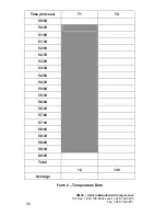
Table 12 – Temperature modification
Example of Return Line Sizing:
inputs
startup/warm-up flow
14 GPM
maximum flow
14 GPM
climate type
extreme cold
oil type
AW32 with tank and suction line
preheat
line length
3 ft
hose size selection
from Table 10
line size 3/4”
from Table 11
need to upsize to 1-1/4”
conclusion
use 1-1/4” return line


