background image

EN - 8

1. Install “Installation Wizard 2” from the Software Utility directory on the software CD.
2. The program will conduct an analysis of your network environment. After your network is ana-

lyzed, please click on the “Next” button to continue the program.

Assigning an IP Address

4

3.  The program will search for VIVOTEK Video Receivers, Video Servers, and Network Cameras 

on the same LAN.

4.  After a brief search, the main installer window will pop up. Double-click on the MAC address 

that matches the one printed on the camera label or the serial number on the package box 

label to open a browser management session with the Network Camera.

For further setup, please refer to the user's manual on the software CD.
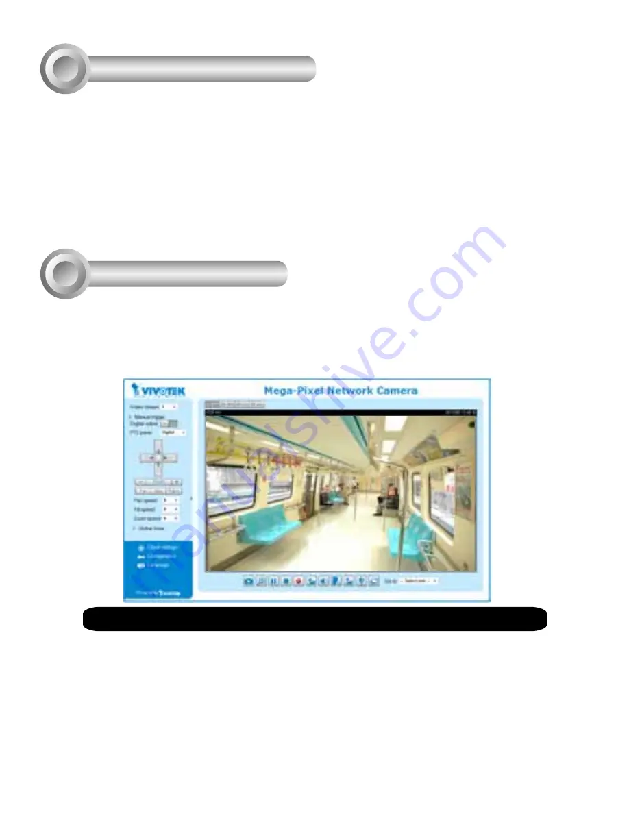
Ready to Use 

5

1.  A browser session with the Network Camera should prompt as shown below.

2.  You should be able to see live video from your camera. You may also install the 32-channel 

recording software from the software CD in a deployment consisting of multiple cameras. For 

its installation details, please refer to its related documents.

Содержание Supreme MD8531H

Страница 1: ......

Страница 2: ...urfaces Do not touch the Network Camera during a lightning storm Do not drop the Network Camera Do not insert sharp or tiny objects into the Network Camera Replacing or failing to properly install the...

Страница 3: ...531H IMPORTANT Record the MAC address before installing the camera Screw Holes Physical Description 2 Inner View Outer View Lens MicroSD SDHC Card Slot Waterproof Level IP66 Reset button Status LED Sc...

Страница 4: ...rdware Installation 3 Tamper proof Screw Camera Base Plastic Cover 2 1 RJ45 Cable Dimension 2 Strip part of the sheath from the Ethernet cable 1 Drill a hole on the rubber seal plug and insert an Ethe...

Страница 5: ...orange solid g white green stripe B blue solid b white blue stripe G green solid br white brown stripe BR brown solid 3 You will need an RJ45 crimping tool to attach the Ethernet wires to a connector...

Страница 6: ...s through the rubber seal as shown below Tighten up and install the connector when done 1 DI 2 DI 3 DO 4 DO 5 Audio GND 6 Audio Out 2 Use a small size flat blade screwdriver to secure IO wires to the...

Страница 7: ...Connect the terminal block to the camera NOTE 1 This equipment is only to be connected to PoE networks without routing to outside plants 2 For PoE input connection use only UL listed I T E with PoE o...

Страница 8: ...holes if necessary 3 This Network Camera can be mounted with the cable routed through the ceiling wall or from the side If you want to feed the cable through the ceiling wall drill a cable hole A as...

Страница 9: ...ler window will pop up Double click on the MAC address that matches the one printed on the camera label or the serial number on the package box label to open a browser management session with the Netw...

Страница 10: ...une the Camera Focus The focus of this network camera is set from 1 0 meter to infinity by factory default If you want to focus on objects closer than 1 0m or the lens has lost focus please fine tune...

Страница 11: ...the dome cover to under the retainer clip Please replace the desiccant whenever you open the dome cover Retainer clip Desiccant bag 4 7 8 4 Use the adjustment tool to adjust the lens focus by rotating...

Страница 12: ......

Страница 13: ......

Отзывы: