VIVOTEK–Built with Reliability
User's Manual–15
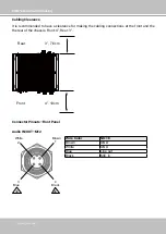
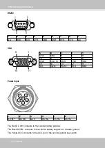
Connector Pinouts–Rear Panel
1
2
3
4
G
5
6
7
8
G
1
ALARM OUT
2
3
4
10
8
8
7
6
5
4
3
2
1
DI GND
DI8
DI7
DI6
DI5
DI GND
DI4
DI3
DI2
DI1
20
19
18
17
16
15
14
13
12
11
N/A
N/A
DO4_
COM
DO4_
NO
DO3_
COM
DO3_
NO
DO2_
COM
DO2_
NO
DO1_
COM
DO1_
NO
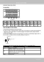
Terminal Block
Terminal Block Connections
The terminal block pinouts is shown as follows:
Connect your relay or external devices’ signal wires to the system, the system will automatically
detect the current signal status. You can then trigger the external devices using the DI/DO
panel on the live view.
You can also configure the system alarm setting for the system to automatically trigger a DO on
the occurrence of system events. See Alarm settings on page 107.
Normally Open
pin
Common pin
Normally Closed
pin
Coil
The pins are listed and described from left to right as shown in the drawing above.
Pin
Description
NOTE
DI no. 1 ~ 8
Open/short to GND
G
Pins #1~4 share a common ground.
Pins #5~8 share a common ground.
NO
Normally open. Use the DO trigger
buttons on the live view window to
trigger the digital output.
COM
Common pin
Содержание NV9311P
Страница 63: ...VIVOTEK Built with Reliability User s Manual 63 ...
Страница 128: ...VIVOTEK Built with Reliability 128 User s Manual ...

