background image

EN - 5

English

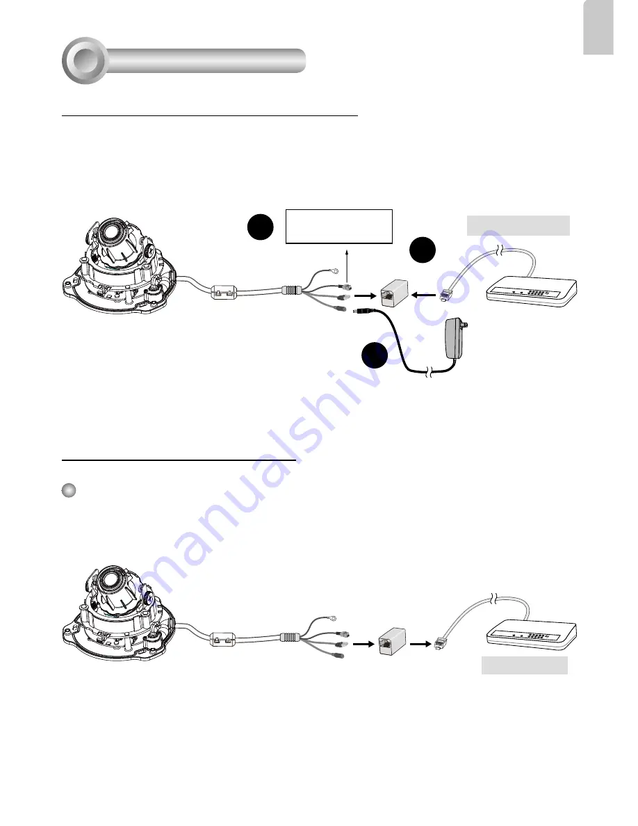
General Connection (without PoE)

Network Deployment

4

+ : Digital input

-  : Digital input

POWER

COLLISION

LINK

RECEIVE

PARTITION

1

2

3

4

5

2

3

Ethernet Switch

1

1. If you have external DI devices, make the connection from general I/O terminal block.

2. Use the supplied RJ45 female/female coupler to connect the Network Camera to a 

switch.

Use a Category 5 Cross Cable when Network Camera is directly connected to PC.

3. Connect the supplied power cable from the Network Camera to a power outlet.

Power over Ethernet (PoE) 

POWER

COLLISION

LINK

RECEIVE

PARTITION

1

2

3

4

5

PoE Switch

When using a PoE-enabled switch

This Network Camera is PoE-compliant, allowing transmission of power and data via a 

single Ethernet cable. Follow the below illustration to connect the Network Camera to a 

PoE-enabled switch via Ethernet cable.

Содержание FD8131V

Страница 1: ...Quick Installation Guide English Espa ol Portugu s Fran ais Deutsch Italiano T rk e Polski esky Svenska FD8131V Fixed Dome Network Camera H 264 Vandal proof IP66...

Страница 2: ...perature Keep the Network Camera away from direct sunlight Do not place the Network Camera in high humidity environments Warning Before Installation Do not place the Network Camera on unsteady surface...

Страница 3: ...Female Female Coupler Screwdriver Screws Clamp Core 510000221G Package Contents 1 Quick Installation Guide Warranty Card Physical Description 2 Lens Reset Button General I O Terminal Block Status LED...

Страница 4: ...Taiwan This device complies with part 15 of the FCC rules Operation is subject to the following two conditions 1 This device may not cause harmful interference and 2 this device must accept any interf...

Страница 5: ...g wall or from the side If you want to feed the cable through the ceiling wall drill a cable hole A as shown in the above picture 4 Hammer the supplied plastic anchors into the holes 5 Align the two h...

Страница 6: ...he Network Camera to a switch Use a Category 5 Cross Cable when Network Camera is directly connected to PC 3 Connect the supplied power cable from the Network Camera to a power outlet Power over Ether...

Страница 7: ...ANT Although the camera and the cable gland on the camera s end are waterproof the cable molding at the other end is not waterproof Measures should be taken to prevent water from leaking in through th...

Страница 8: ...up Double click on the MAC address that matches the one printed on the camera label or the S N number on the package box label to open a browser management session with the Network Camera Assigning a...

Страница 9: ...ule up and down Upon completion tighten the screws 3 Turn the lens to adjust the image orientation Adjusting the Lens 7 1 2 3 Loosen Tighten Pan 350 Rotate 340 Tilt 70 The sophisticated 3 axis mechani...

Страница 10: ...rientation Align the side cover or side cutout with where the cable comes out from the camera Push the dome cover to join with the camera 4 Finally make sure all parts of the camera are securely insta...

Страница 11: ...All specifications are subject to change without notice Copyright 2012 VIVOTEK INC All rights reserved c P N 625018600G Rev 1 0...

Отзывы: